Cleaning device and method for hollow fiber gas separation membrane module

A gas separation membrane and cleaning device technology, which is applied in the field of separation membrane cleaning, can solve problems such as damage to the combination of the support layer and the functional layer, scrapping of the membrane module, and rupture of the membrane filament at the junction of the membrane filament and the sealant, etc., so as to improve the cleaning effect and Efficiency, performance thorough restoration, and the effect of shortening the cleaning time

Active Publication Date: 2017-05-10
TIANBANG NAT ENG RES CENT OF MEMBRANE TECH
View PDF9 Cites 10 Cited by
  • Summary
  • Abstract
  • Description
  • Claims
  • Application Information

AI Technical Summary

Problems solved by technology

[0006] The cleaning device and method in the above patents have obvious technical shortcomings: 1. Most of the gas separation membranes are composite membranes formed by the combination of support layer and functional layer by physical adsorption. Cleaning with ultrasonic vibration or high-pressure airflow (especially backwashing) may cause Destroy the bond between the support layer and the functional layer, resulting in the peeling of the two layers, and even the scrapping of the membrane module
2. Due to the high packing density of the hollow fiber gas separation membrane module, the small diameter of the membrane filament, the relatively closed interior of the membrane module, the capillary effect of the membrane filament and the swelling and adsorption of the membrane material, a large amount of cleaning agent remains in the cleaned membrane module. Solvents such as sodium hypochlorite and sodium citrate will precipitate solids after volatilization, which will cause secondary pollution to the gas separation membrane module and reduce the cleaning efficie...

Method used


Image

  • Cleaning device and method for hollow fiber gas separation membrane module
  • Cleaning device and method for hollow fiber gas separation membrane module
  • Cleaning device and method for hollow fiber gas separation membrane module

Examples


Embodiment 1

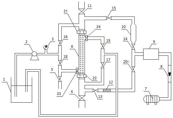
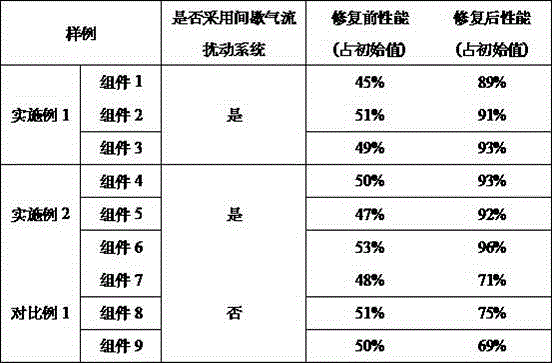
[0032] Use the method for cleaning the hollow fiber gas separation membrane module disclosed in the present invention to clean the polysulfone hollow fiber gas separation membrane module and test the initial performance of the membrane module. The stop frequency is 10 times / minute, and the flow rate of the disturbed airflow is 10 m 3 / h, disturbed air flow cleaning for 1 hour, positive and negative two-way pressure cleaning time is 1 hour, cleaning pressure is 0.1MPa, step temperature purge flow rate is 50m 3 / h, the purging temperature is 60, 80, 100°C, and the purging time is 2, 2, 1 hour respectively. Clean the three membrane modules of the same batch and similar pollution degree according to the above-mentioned specific operation process, which are modules 1-3 respectively. After the cleaning, the performance of the membrane modules is tested, and the results are shown in Table 1.

Embodiment 2

[0034] Use the method for cleaning the hollow fiber gas separation membrane module disclosed in the present invention to clean the polysulfone (PSF) hollow fiber gas separation membrane module and test the initial performance of the membrane module. The start-stop frequency of the medium airflow is 15 times / min, and the flow rate of the disturbed airflow is 20 m 3 / h, disturbed air flow cleaning for 2 hours, positive and negative two-way pressurized cleaning time is 1 hour, cleaning pressure is 0.1MPa, step temperature purge flow rate is 50m 3 / h, the purging temperature is 60, 80, 100 o C, the purging time is 2, 2, 1 hour respectively. Clean the three membrane modules of the same batch and similar pollution degree according to the above-mentioned specific operation process, which are modules 4-6 respectively. After the cleaning, the performance of the membrane modules is tested, and the results are shown in Table 1.

Embodiment 3

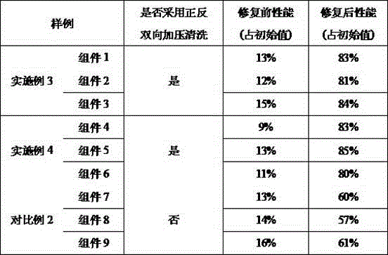
[0041] Use the method for cleaning the hollow fiber gas separation membrane module disclosed in the present invention to clean the polyimide hollow fiber gas separation membrane module and test the initial performance of the membrane module. The frequency of airflow start and stop is 10 times / min, and the flow rate of disturbed airflow is 15 m 3 / h, disturbed air flow cleaning for 1.5 hours, positive pressure cleaning time for 3 hours, reverse pressure cleaning time for 1 hour, cleaning pressure of 0.1MPa, step temperature purge flow rate of 70m 3 / h, the purging temperatures are 60, 90, and 120°C, and the purging times are 2, 1, and 2 hours, respectively. Three membrane modules (modules 1-3) of the same batch and with similar pollution levels were cleaned according to the above-mentioned specific operation process for parallel experiments. After cleaning, the performance of the membrane modules was tested. The results are shown in Table 2.


PUM


Abstract

The invention discloses a cleaning device and method for a hollow fiber gas separation membrane module. The cleaning device is formed by the membrane module, a positive and negative bidirectional cleaning system, a ladder temperature purge system and an intermittent flow disturbance system. The positive and negative bidirectional cleaning system consists of a cleaning fluid tank, a cleaning pump, a pressure gauge, a positive and negative bidirectional cleaning pipeline and a blowoff valve. The ladder temperature purge system consists of an air compressor, a flowmeter, a control system, a heater, a purge pipeline and a blowoff valve. The intermittent flow disturbance system consists of an air compressor, a flowmeter, a control system, a disturbance gas flow generator, a check valve and a gas escape valve. The device disclosed by the invention can clean membrane modules in different pollution conditions; by a comprehensive cleaning effect of the intermittent flow disturbance system, the positive and negative bidirectional cleaning system and the ladder temperature purge system, performance of the membrane module is entirely repaired. The cleaning device and method are high in cleaning efficiency for the membrane module, good in effect, low in cost, simple in process and convenient to operate, and save enormous cost of replacing the membrane module.

Description

technical field [0001] The invention relates to the technical field of separation membrane cleaning, in particular to a cleaning device and method for a hollow fiber gas separation membrane module. Background technique [0002] Membrane separation technology is an efficient, fast and energy-saving new separation technology that can adapt to the requirements of contemporary new industries, so it develops relatively rapidly and is considered to be a high-tech with great development prospects in the 21st century. As an important part of membrane separation technology, gas separation membrane has been widely used in air separation, hydrogen recovery, natural gas removal of acid gas (H 2 S, CO 2 etc.), organic vapor (VOCs) recovery and gas dehumidification and other industries. According to the "Twelfth Five-Year Plan" development guide for the separation membrane industry, the world's gas separation membrane market is expected to rise to 760 million US dollars per year in 2020...

Claims


Application Information

Patent Timeline
IPC IPC(8): B01D65/02B01D63/02B01D46/54B01D46/00B01D65/10
CPCB01D46/543B01D63/02B01D65/02B01D65/10B01D2273/20B01D2273/18B01D46/68B01D46/70B01D46/72
Inventor 张志超葛洁徐连禄徐徜徉张桂花窦炜康战辉
Owner TIANBANG NAT ENG RES CENT OF MEMBRANE TECH
Why Eureka
Try Eureka