Exhaust emission method and exhaust emission device
A waste gas emission and waste gas technology, which is applied in the direction of cleaning methods and appliances, chemical instruments and methods, and dust removal, can solve problems such as disrupted production plans, waste of raw materials and energy, and poor air pollutant diffusion conditions. Strong continuous operation ability, high degree of automation, and the effect of improving the diffusion ability
- Summary
- Abstract
- Description
- Claims
- Application Information
AI Technical Summary
Problems solved by technology
Method used
Image
Examples
Embodiment 1
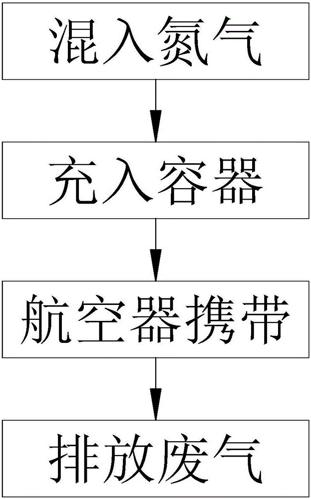
[0047] figure 1 It is a flow chart of the exhaust gas discharge method of Embodiment 1 of the present invention.
[0048] A waste gas discharge method, mixing gas with a density lower than air into the waste gas, filling the mixed gas into a container together, and then making the container and the mixed gas rise together.
[0049] By mixing gas with a lower density than air into the exhaust gas, using the buoyancy of the air, the exhaust gas and the inflated gas are integrated with the container to rise to a high altitude, and even rise to the stratosphere, and the container discharges the exhaust gas, thereby greatly improving the waste gas. The diffusion ability in calm weather significantly improves the air quality at low altitudes.
[0050] Preferably, the gas mixed into the waste gas is nitrogen.
[0051] By filling the above-mentioned gas, the overall density of the container, the waste gas and the mixed gas can be made lower than that of the air, which is easy to be ...
Embodiment 2
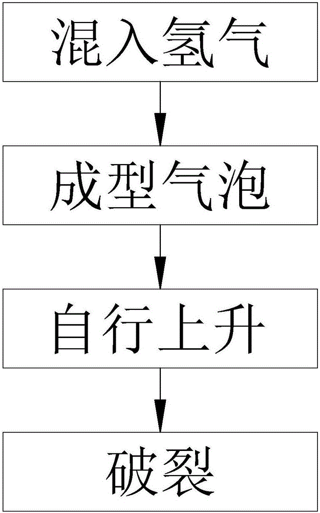
[0063] figure 2 It is a flow chart of the exhaust gas discharge method of Embodiment 2 of the present invention.
[0064] The difference between this embodiment and Embodiment 1 is that the gas mixed into the waste gas is hydrogen. The container is an air bubble, and the air bubble is composed of an air bubble forming material, and the air bubble forming material is a foam liquid, a surface active agent, a film forming agent, and a mixture of the film forming agent and the foam agent.
[0065] Filling with hydrogen can make the overall density of the container, waste gas and mixed gas less than that of air, which is easy to be lifted up by the buoyancy of the air.
[0066] The use of air bubbles as a container can continuously and uninterruptedly collect waste gas, fill it with waste gas, and continuously generate bubbles during the process of exhaust gas discharge. It has a high degree of automation and strong continuous operation ability.
[0067] Still further preferably...
Embodiment 3
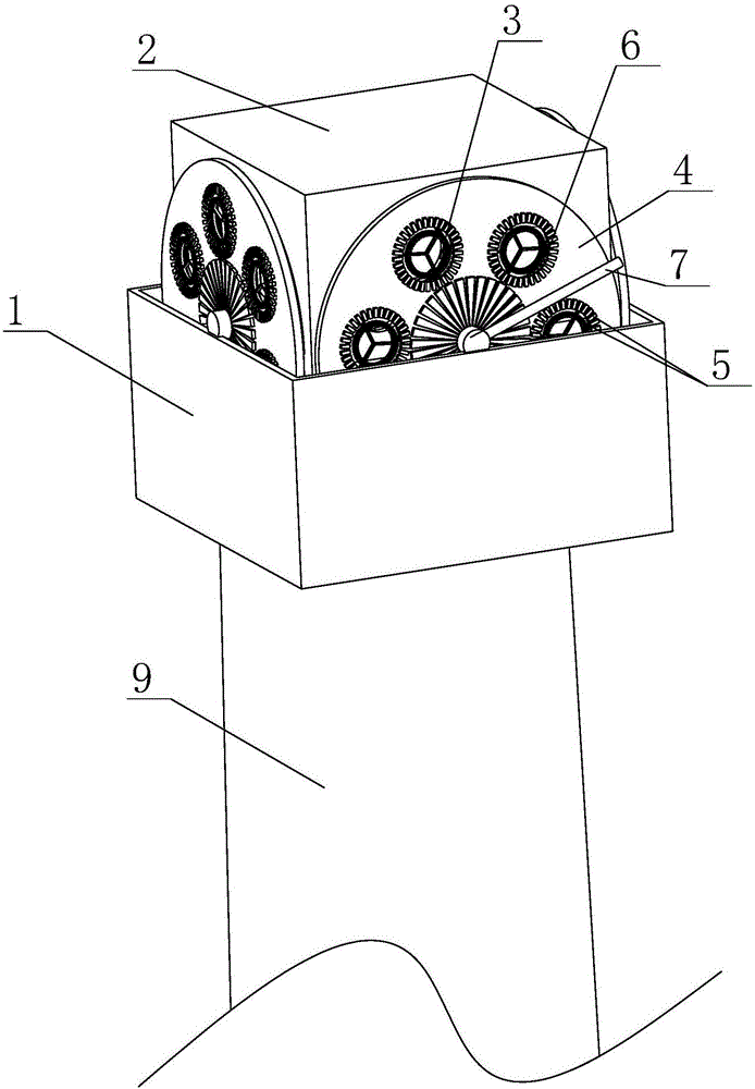
[0074] image 3 is a schematic diagram of the waste gas discharge device of Embodiment 3 of the present invention; Figure 4 yes image 3 The schematic diagram of the exhaust gas discharge device in the figure after removing the turntable on one side; Figure 5 yes Figure 4 In the case of the case, the schematic diagram after adding the hydrogen delivery pipe is added. In the figure, the same reference numerals as those used in the above-mentioned embodiments still follow the definition of the reference numerals in the above-mentioned embodiments. The meanings of the new reference signs appearing in the figure are as follows: 1. Tank body; 2. Rectangular body; 3. Exhaust gas flow hole; 4. Turntable; 5. Boss; 6. Forming port; 7. Bubble lever; 8. Hydrogen delivery pipe; 9. Chimney.
[0075] This embodiment is a device for realizing the method described in Embodiment 2:
[0076] A waste gas discharge device for realizing the above waste gas discharge method, the waste gas ...
PUM
 Abstract
Description
Claims
Application Information
 - R&D
- Intellectual Property
- Life Sciences
- Materials
- Tech Scout
- Unparalleled Data Quality
- Higher Quality Content
- 60% Fewer Hallucinations
Browse by: Latest US Patents, China's latest patents, Technical Efficacy Thesaurus, Application Domain, Technology Topic, Popular Technical Reports.
© 2025 PatSnap. All rights reserved.Legal|Privacy policy|Modern Slavery Act Transparency Statement|Sitemap|About US| Contact US: help@patsnap.com


