
Conveying system

A conveying system and diverting device technology, which is applied in the direction of conveyors, conveying bulk materials, transportation and packaging, etc., can solve problems such as difficult to replace cleanly, affect fluid conveyance, and high pressure loss, and achieve convenient maintenance and replacement in the later stage, and steam density Uniform and stable delivery pressure

Inactive Publication Date: 2017-05-10
黄素珍
View PDF0 Cites 2 Cited by
  • Summary
  • Abstract
  • Description
  • Claims
  • Application Information

AI Technical Summary

Problems solved by technology

[0004] However, the method of fluid delivery in the commonly used optical fiber preform manufacturing process has the following disadvantages: 1. Due to the layout of the system equipment, there is a lot of pressure loss, and it does not use the later system maintenance and transformation; 2. The fluid material inside the system device is easy to 3. In the process of transporting fluid raw materials, the difference in carrier gas quality and unstable flow control will lead to ineffective deposition. The vapor carried by the carrier gas after entering the raw material is a mixture of different media. Therefore, The density of the vapor cannot be guaranteed to be uniform, resulting in deposition failure

Method used


Image

  • Conveying system

Examples


Embodiment 1

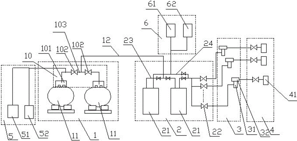
[0024] Such as figure 1 As shown, a conveying system is disclosed in this embodiment, which sequentially includes a raw material supply device 1, a flow diversion device 2, a vaporization device 3 and a deposition device 4, the above-mentioned raw material supply device 1, flow diversion device 2, vaporization device 3 and deposition device 4 They are connected by pipelines to form fluid raw material delivery pipelines, and the ends of the above-mentioned deposition devices 4 are connected to various material consumption points.

[0025] The above-mentioned vaporization device 3 is the core part of the system, and is the core equipment for whether the whole system can produce qualified preforms, and can directly affect the optical properties of the preforms after subsequent deposition. Specifically, the vaporization device 3 includes several raw material heating tanks 31 , a delivery valve group panel 32 and a mass flow meter arranged on the feeding ports of the raw material h...


PUM


Abstract

The invention discloses a conveying system. The conveying system sequentially comprises a raw material supply device, a flow diversion device and a deposition device. The raw material supply device, the flow diversion device and the deposition device are connected through pipelines to form a fluid raw material conveying pipeline, the tail end of the deposition device is connected to material use points, and a vaporization device is arranged between the flow diversion device and the deposition device and comprises multiple raw material heating tanks, conveying valve bank panels arranged on feed ports of the raw material heating tanks, and mass flow meters. The vaporization device carries out deposition in the mode that raw materials are heated to generate steam, the steam density is uniform, the deposition effect is good, and the optical performance of preforms prepared after deposition is completed is good.

Description

technical field [0001] The present invention relates to the field of optical fiber production, relates to an auxiliary device for manufacturing optical fiber preform rods, and more specifically relates to a delivery system. Background technique [0002] Generally, silicon tetrachloride and germanium tetrachloride are used as liquid raw materials in the manufacturing process of optical fiber preforms. The above two liquid raw materials are used to deposit the core layer and cladding of preforms. The quality of optical fiber preforms is related to the quality of raw material deposition. Closely related, the key factors affecting the quality of raw material deposition include: raw material pressure fluctuations, flow fluctuations and temperature fluctuations, and the above three factors are also closely related, the main factor leading to raw material pressure fluctuations is the liquid raw material delivery system. [0003] There are two main methods of fluid transportation co...

Claims


Application Information

Patent Timeline
Patent Type & Authority Applications(China)
IPC IPC(8): B65G53/16
CPCB65G53/16
Inventor 黄素珍
Owner 黄素珍
Learn More