
Low nitrogen oxide burner of fuel gas heating water heater
A low-nitrogen oxide, gas heating technology, applied in gas fuel burners, burners, combustion methods, etc., can solve problems such as difficulty in adjusting the ratio of rich gas to light gas, complicated burner structure, and occurrence of acid rain, etc. The effect of strong oxygen supply and gas mixed flow capacity, improved combustion stability and low cost
- Summary
- Abstract
- Description
- Claims
- Application Information
AI Technical Summary
Problems solved by technology
Method used
Image

Examples
Embodiment Construction
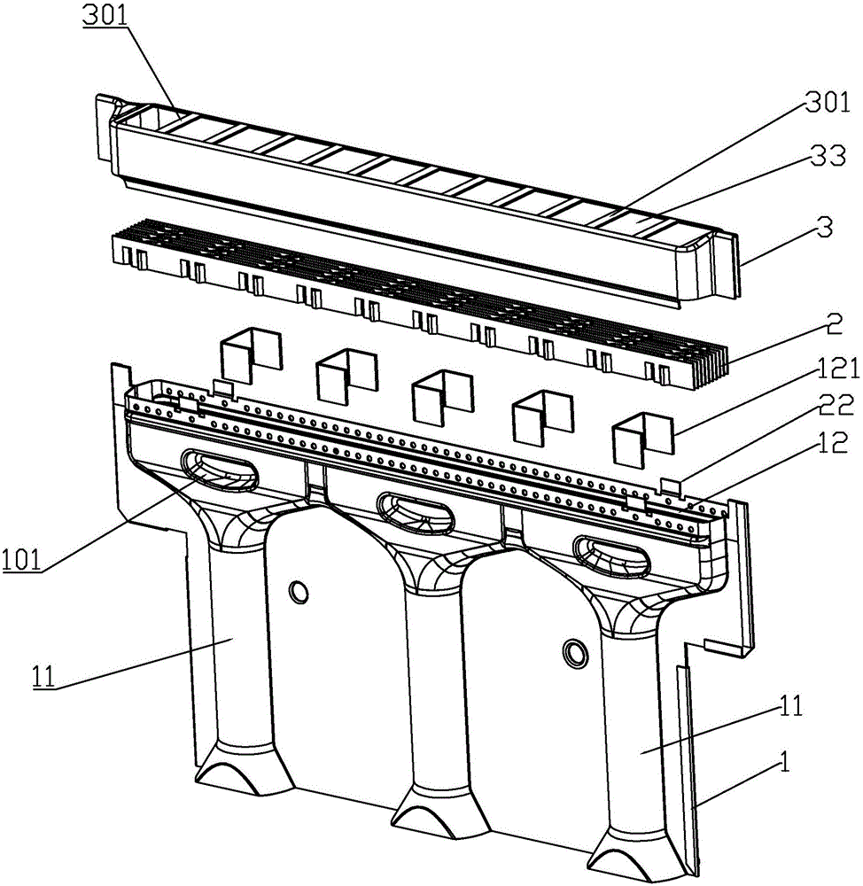
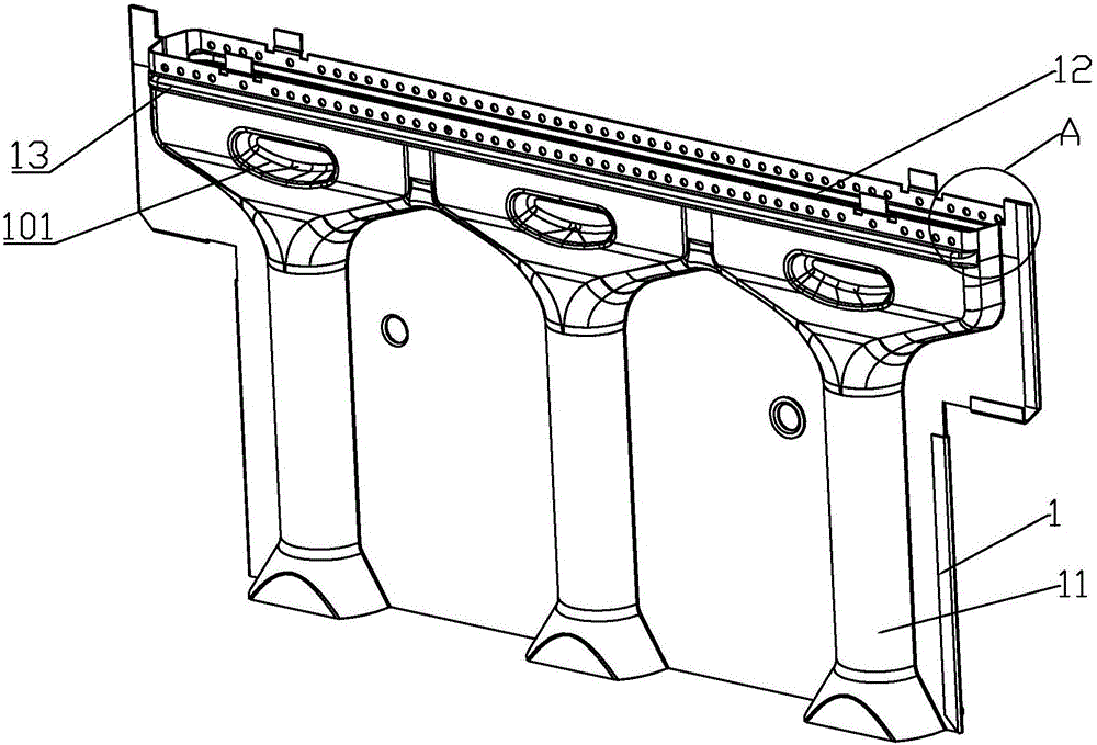
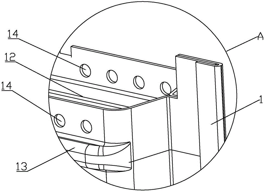
[0033]A low nitrogen oxide burner for a gas heating water heater. The low nitrogen oxide burner includes a gas mixing shell 1, a fire hole grille 2, and a burner shell cover 3; the gas mixing shell 1 is provided with A number of gas mixed intake injection pipes 11, the bottom end of the gas mixed intake injection tube 11 is provided with a gas injection port 111; the top of the gas mixed housing 1 is provided with a mixed gas groove 12, and The groove 12 communicates with the gas mixing intake injection pipe 11; the front and rear shell walls of the upper part of the gas mixing shell 1 are provided with ribs 13, which are formed between the ribs 13 and the top plate tail of the gas mixing shell 1. There is a step 131; several horizontal gas outflow holes 14 are arranged on the front and rear shell walls of the top plate tail of the gas mixing shell 1; the fire hole grid 2 is fixed on the slot of the gas mixture groove 12, and the fire hole grid The width of the grid 2 is great...
PUM
 Abstract
Description
Claims
Application Information