Gated fiber optic Raman spectrometer based on laser ranging and automatic focusing

A Raman spectrometer and automatic focusing technology, applied in the field of spectral measurement, can solve problems such as increasing the difficulty of operation and restricting the use of equipment, and achieve the effect of improving mechanical stability and reliability

Active Publication Date: 2020-12-11
BEIJING INFORMATION SCI & TECH UNIV
View PDF14 Cites 0 Cited by
  • Summary
  • Abstract
  • Description
  • Claims
  • Application Information

AI Technical Summary

Problems solved by technology

This close-fitting measurement greatly limits the use of the device
For example, the Raman spectrometer cannot quickly obtain the mineral composition of a certain area like the infrared imaging spectrometer. In addition, if the Raman spectrometer is used to analyze the material composition on the surface of the planet on an alien lander or rover, an additional manipulator is required to place the sample on the surface of the planet. In the sample room, it increases the difficulty of operation

Method used


Image

  • Gated fiber optic Raman spectrometer based on laser ranging and automatic focusing
  • Gated fiber optic Raman spectrometer based on laser ranging and automatic focusing

Examples


Embodiment 1

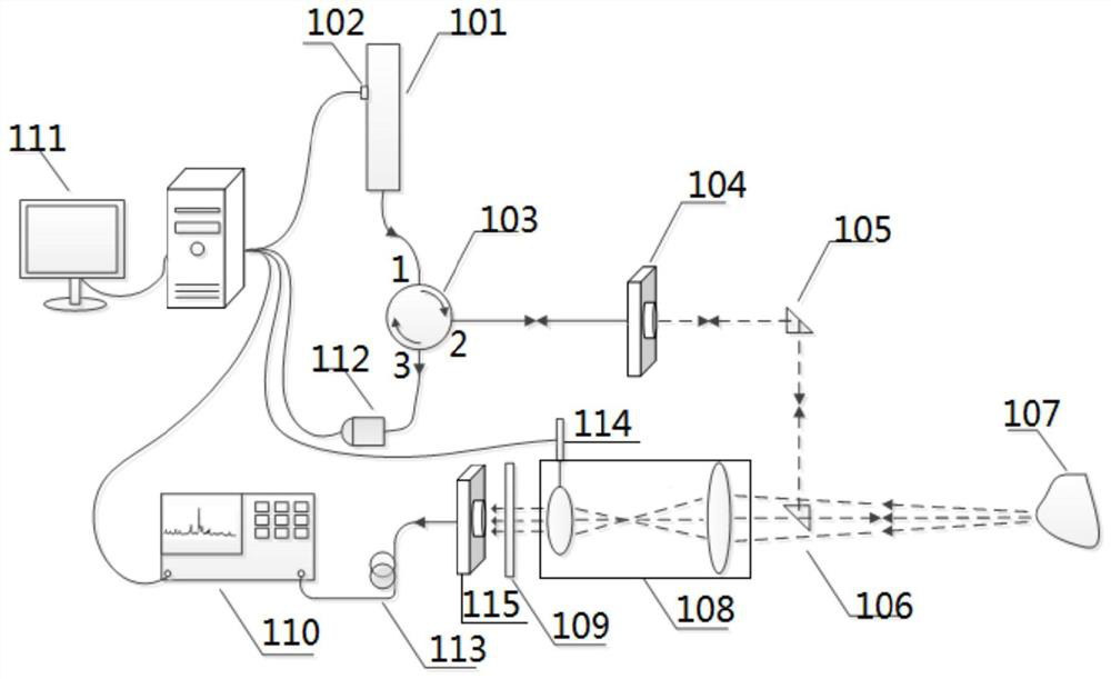
[0042] A gated optical fiber Raman spectrometer based on laser ranging and automatic focusing includes a laser detection system, a Raman scattered light collection system, and a signal trigger delay and data processing control system.

[0043] The laser detection system is divided into a laser emission detection system and a laser emission detection system.

[0044] The laser emission detection system is composed of a pulsed laser 101, a circulator 103, a first collimator 104, a reflective prism 105, a dichroic prism 106 and a sample 107; the pulsed laser 101 emits a laser beam in the order of ns and enters the port of the circulator 103 1. The laser beam at port 2 of the circulator 103 enters the first collimator 104 to turn the laser beam into parallel light and enters the reflective prism 105. After passing through the reflective prism 105, the propagation direction of the laser beam rotates 90° clockwise and enters the dichroic prism 106 , the propagating direction of the la...

Embodiment 2

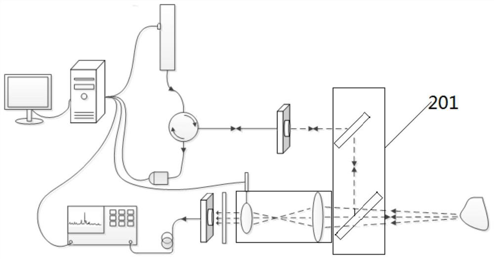
[0060] figure 2 It is a schematic structural diagram of Embodiment 2 of the gated fiber optic Raman spectrometer based on laser ranging and automatic focusing of the present invention. The difference between this embodiment and Embodiment 1 is that: the reflective prism 105 and the dichroic prism 106 are changed. Such as figure 2 As shown, in this embodiment, the included angle between the reflective prism and the first collimator is 45°, and the dichroic prism is placed relatively parallel to the reflective prism in the longitudinal direction.

[0061] The positional relationship of the prism group 201 can also be that the included angle between the reflective prism and the first collimator is 45°, and the dichroic prism is vertically placed relative to the reflective prism in the longitudinal direction; the reflective prism and the dichroic prism can be placed separately Two groups of prisms can also be installed in combination to realize the reflection or transmission o...


PUM


Abstract

The invention discloses a gating optical fiber Raman spectrometer based on laser ranging automatic focusing. The gating optical fiber Raman spectrometer comprises a laser detection system, a Raman scattered light collecting system and a signal trigger delay and data processing control system. The optical fiber Raman spectrometer is composed of a pulse laser, a circulator, a first collimator, a reflecting prism, a dichroic prism, a photoelectric detector telephoto lens system, a second collimator, an optical filter and a gating spectrometer. The gating optical fiber Raman spectrometer can perform detection directly and quickly within a certain distance; whether laser spots irradiate an object can be automatically determined through a photoelectric detector to perform automatic delay control; automatic focusing is performed quickly through an electronic control focusing device of the telephoto lens system; optical fiber transmission is adopted, and mechanical stability and reliability of a device are greatly improved.

Description

technical field [0001] The invention relates to the technical field of spectrum measurement, in particular to a gated optical fiber Raman spectrometer based on laser ranging and automatic focusing. Background technique [0002] The Raman spectral line was first discovered by the Indian physicist Raman in 1928 when he was studying the scattering of liquid benzene. It is a kind of scattering spectrum. When light is irradiated on an object, part of the light will be inelastically scattered. In addition to the same elastic component as the incident light (Rayleigh scattering), the scattered light also has components that increase and decrease in frequency compared to the incident light. The frequency The reduced component is called the Stokes line, and the frequency-increased component is called the anti-Stokes line, and the frequencies of the two components are symmetrically distributed on both sides of the excitation light frequency. [0003] The Raman effect is mainly the re...

Claims


Application Information

Patent Timeline
Patent Type & Authority Patents(China)
IPC IPC(8): G01N21/65
CPCG01N21/65
Inventor 姚齐峰祝连庆张雯娄小平董明利李红辛璟焘
Owner BEIJING INFORMATION SCI & TECH UNIV
Why Eureka
Try Eureka