Fet-bipolar transistor combination

A bipolar transistor, transistor technology, applied in transistors, semiconductor devices, electro-solid devices, etc., can solve problems such as disturbing circuit operation

Active Publication Date: 2017-05-17
ANALOG DEVICES INT UNLTD
View PDF10 Cites 0 Cited by
  • Summary
  • Abstract
  • Description
  • Claims
  • Application Information

AI Technical Summary

Problems solved by technology

However, it is generally desired that the drive load provided by such transistors be as small as possible, and this tends to be a problem with relatively large MOSFETs, since although they hold the gate at a constant voltage, the gate has a relatively large capacitance, and thus in The current flowing into and out of the gate during transistor switching can result in large transient current flows that can disrupt the operation of other circuits or cause noise in them due to such large current-induced fluctuations in the supply rail voltage

Method used


Image

  • Fet-bipolar transistor combination
  • Fet-bipolar transistor combination
  • Fet-bipolar transistor combination

Examples


Embodiment Construction

[0028] FET-Bipolar Transistor Combination

[0029] The following detailed description of certain embodiments presents various descriptions of specific embodiments. However, the innovations described herein can be implemented in many different ways, eg as defined and covered by the claims. In this specification, reference is made to the drawings, wherein like reference numbers may indicate identical or functionally similar elements. It should be understood that elements shown in the figures are not necessarily drawn to scale. Furthermore, it will be appreciated that certain embodiments may include more elements than shown in the figures and / or a subset of elements shown in the figures. Furthermore, some embodiments may combine features from two or more figures in any suitable combination.

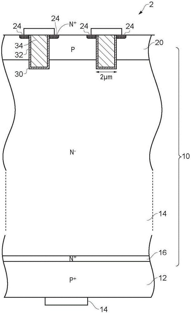
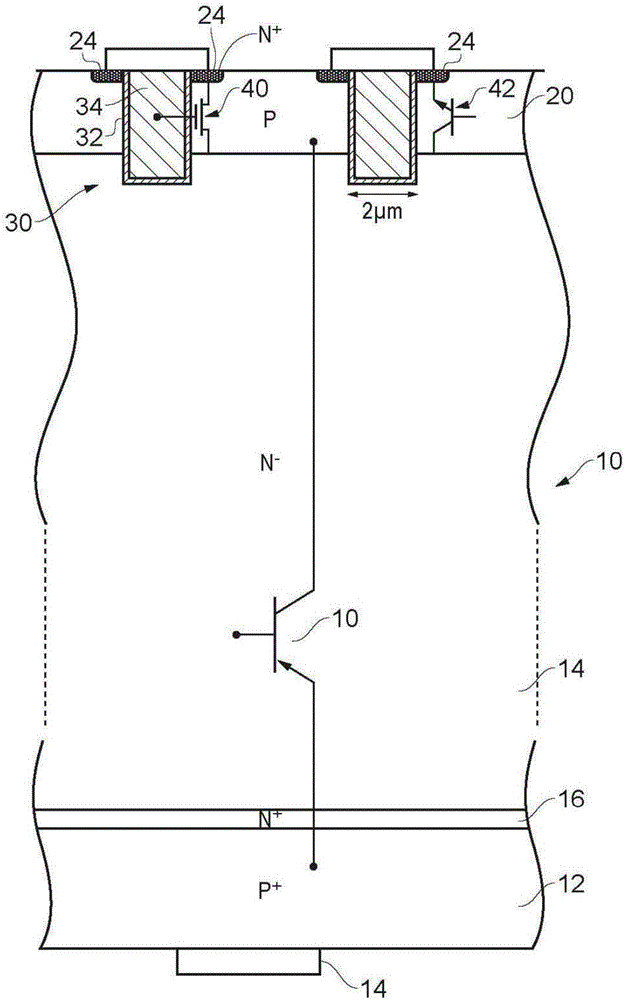
[0030] Some transistor structures are shown in the figure. Various regions of different doping concentrations and dopant types are shown in the figures and, for ease of illustration, rep...


PUM

PropertyMeasurementUnit
relative permittivityaaaaaaaaaa

Abstract

The invention relates to FET-bipolar transistor combination. A transistor switch device is provided that exhibits relatively good voltage capability and relatively easy drive requirements to turn the device on and off. This can reduce transient drive current flows that may perturb other components.

Description

technical field [0001] The present disclosure relates to combinations of field effect transistors and bipolar transistors. Background technique [0002] There is often a need to be able to switch relatively high voltages, often up to and in the range of 200 volts to 300 volts. Transistors that enable this can be integrated into integrated circuit packages with lower voltage processing and control circuitry. In many cases, it is convenient and cost effective to have such high voltage transistors on the same die as the lower voltage control circuitry. As a result, it is highly desirable to make all connections to such high voltage transistors on the same side of the wafer. Switching applications in this voltage range include motor control and inverters, dimmers, automotive switching where transient voltages due to inductive loads can occur, and overall mains voltage related switching in industrial and household appliances and for power supply for such appliances. [0003] ...

Claims


Application Information

Patent Timeline
Patent Type & Authority Applications(China)
IPC IPC(8): H01L25/07
CPCH01L25/071H03K17/0828H03K17/567H01L27/0705H01L27/1203H01L29/7803H01L29/7809H01L29/7813H01L29/732H01L29/7812H01L21/823475H01L27/0623H01L29/0804H01L29/0821H01L29/41741H01L29/41766H01L29/66234H01L29/66666H01L29/7302H01L29/7827
Inventor E·J·考尼
Owner ANALOG DEVICES INT UNLTD
Why Eureka
Try Eureka