Lymphocyte extraction device and extraction method
A lymphocyte and extraction device technology, applied in cell dissociation methods, animal cells, sterilization methods, etc., can solve problems such as low work efficiency, pollution, cumbersome and time-consuming operations, and save time, reduce use, and avoid contact. Effect
- Summary
- Abstract
- Description
- Claims
- Application Information
AI Technical Summary
Problems solved by technology
Method used
Image

Examples
Embodiment 1
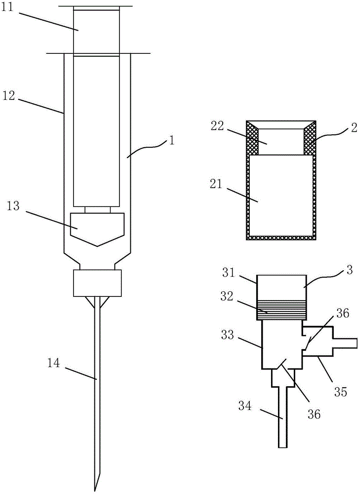
[0023] Embodiment 1: a kind of lymphocyte extraction device, such as Figure 1-Figure 2 As shown, it includes a syringe 1, a separation liquid displacer 2 and a filter washing device 3. The syringe 1 is composed of an outer cylinder 12, a handle 11, a piston 13 and a needle 14. Between the handle and the piston, the outer cylinder The body and the needle can be connected in a detachable manner. The separation liquid displacer 2 is a cylinder structure with a closed lower end and an open upper end. The separation liquid displacer 2 is composed of a liquid storage tank 21 and a connecting section 22. The separation liquid The connection section 22 of the displacer and the outer cylinder can be connected in a detachable manner. The filter and washing device 3 includes a connection cylinder 31, a liquid storage cylinder 33 arranged at the lower end of the connection cylinder and a mixed fiber placed in the connection cylinder. Membrane filter membrane (MCE) 32 with a pore size of ...
Embodiment 2
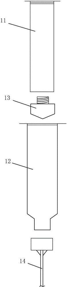
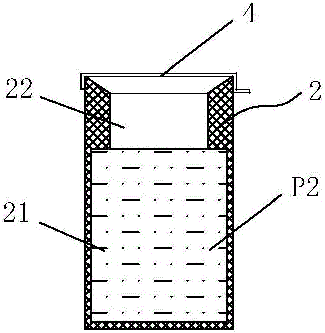
[0025] Embodiment 2: a kind of lymphocyte extraction device, such as image 3 As shown, it includes a syringe 1, a separation liquid displacer 2 and a filter washing device 3, and its basic structure is the same as that of Example 1, the difference is that the liquid storage tank 21 of the separation liquid displacer 2 is also filled with lymph For the cell separation liquid P2, the upper opening of the separation liquid displacer 2 is sealed by a parafilm 4 . When in use, the sealing film 4 can be used directly after being uncovered or pierced, without adding the lymphocyte separation solution P2 inside.
Embodiment 3
[0026] Embodiment 3: a kind of lymphocyte extraction method, such as Figure 4-Figure 5 As shown, using the lymphocyte extraction device as described in Example 1, the specific operation steps are as follows:
[0027] (1) Use the syringe 1 to collect the sample peripheral blood P1, and collect the sample into the outer cylinder 12;
[0028] (2) Remove the handle 11 and needle 14 of the syringe, add the lymphocyte separation liquid P2 to the separation liquid replacer 2, the volume ratio of the amount of the lymphocyte separation liquid to the sample is 1:1, and then add the separation liquid The displacer is installed on the outer cylinder, and then centrifuged, so that the liquid in the outer cylinder is layered into serum P3, mononuclear cell layer P4 and lymphocyte separation liquid P2 from top to bottom. The liquid in the separation liquid displacer is separated from From top to bottom are lymphocyte separation solution P2 and red blood cell P5,
[0029] (3) Remove the s...
PUM
| Property | Measurement | Unit |
|---|---|---|
| Aperture | aaaaa | aaaaa |
Abstract
Description
Claims
Application Information