
Porous substrate and manufacturing method thereof and manufacturing method of thin film transistor

一种薄膜晶体管、制作方法的技术,应用在半导体器件、电固体器件、有机半导体器件等方向,能够解决残胶清理、掩膜版损伤、易混入气体等问题,达到减少污染与浪费、降低制作成本、避免热损伤的效果

Active Publication Date: 2017-05-24
WUHAN CHINA STAR OPTOELECTRONICS TECH CO LTD
View PDF7 Cites 5 Cited by
  • Summary
  • Abstract
  • Description
  • Claims
  • Application Information

AI Technical Summary

Problems solved by technology

[0003] However, there are many defects in the above-mentioned existing technology: (a) During the preparation process of the flexible film layer, gas is easily mixed between the flexible film layer and the glass substrate, and bubbles will be generated in the later Array process and the baking process before evaporation. It will cause light defects in the Array manufacturing process and damage to the mask during the evaporation process; (b) when the flexible OLED device is irradiated by laser light, a large amount of heat will be generated on the surface of the flexible OLED device, which will cause thermal damage to the flexible OLED device Risk; (c) The material of the flexible film layer is mainly polymer, which has a large difference in thermal expansion coefficient between it and the metal electrode on its surface, and there is a risk of peeling off the metal electrode and the flexible film layer; (d) When the laser is irradiated, the laser may pass through the glass substrate and affect the organic light-emitting materials on the glass substrate, such as decomposition, crystallization, etc., especially for bottom-emitting devices; (e) the high price of laser equipment, for mass production line requires a large investment
[0004] Although it is currently possible to use a carrier substrate made of waterproof and breathable materials to overcome the above-mentioned problem of air bubbles, in this technical solution, it is necessary to prepare a flexible film layer in advance, and then use an adhesive to attach it to the surface of the carrier substrate; There are many micropores on the substrate for releasing air bubbles, so the flexible film layer cannot be directly coated on the carrier substrate, and the flexible substrate and the carrier substrate can only be bonded together, which not only increases the complexity of the process, but also The flatness of the flexible film layer has also been greatly challenged; and, because the flexible film layer in the Array process will withstand a high temperature of up to 450 ° C, and due to the light transmittance of the carrier substrate and the scattering of laser light, the carrier substrate It is not suitable for laser peeling method, only heating or mechanical peeling method can be used, which will cause the problem of residual glue cleaning, so this technical solution has high requirements for the carrier substrate and adhesive

Method used


Image

  • Porous substrate and manufacturing method thereof and manufacturing method of thin film transistor
  • Porous substrate and manufacturing method thereof and manufacturing method of thin film transistor
  • Porous substrate and manufacturing method thereof and manufacturing method of thin film transistor

Examples


Embodiment Construction

[0028] Hereinafter, embodiments of the present invention will be described in detail with reference to the accompanying drawings. This invention may, however, be embodied in many different forms and should not be construed as limited to the specific embodiments set forth herein. Rather, the embodiments are provided to explain the principles of the invention and its practical application, thereby enabling others skilled in the art to understand the invention for various embodiments and with various modifications as are suited to particular intended uses. In the drawings, the shapes and dimensions of elements may be exaggerated for clarity, and the same reference numerals will be used throughout to designate the same or like elements.

[0029] It will be understood that although the terms "first", "second", etc. may be used herein to describe various substances, these substances should be limited by these terms. These terms are only used to distinguish one substance from anothe...


PUM

PropertyMeasurementUnit
porosityaaaaaaaaaa
diameteraaaaaaaaaa

Abstract

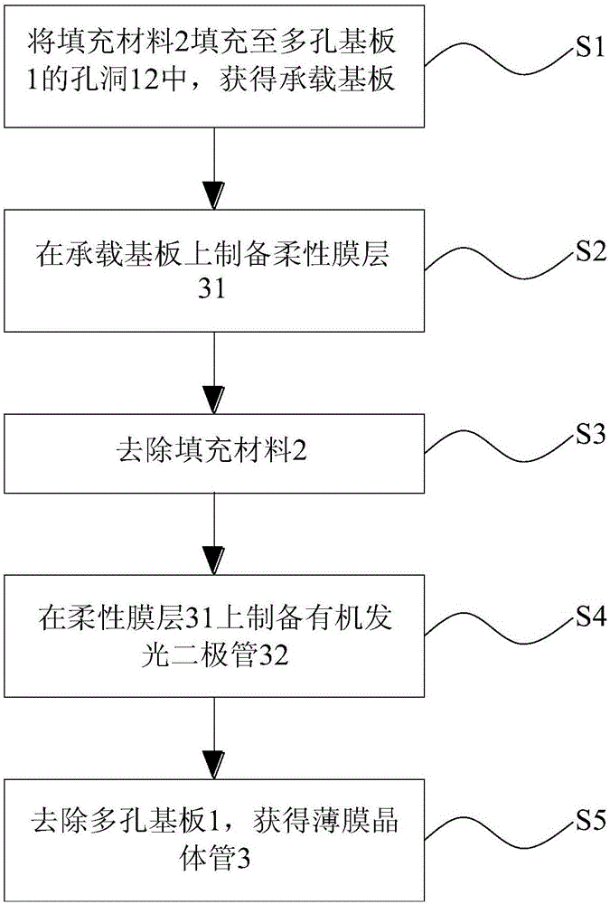
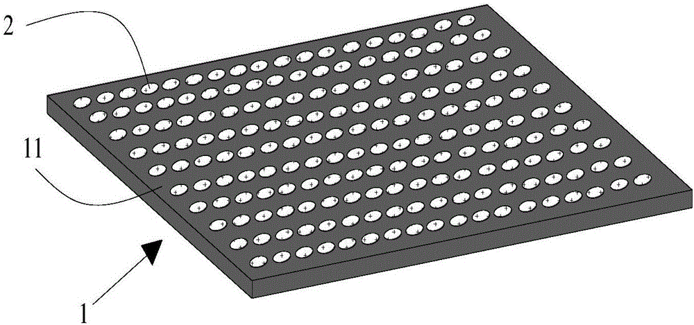
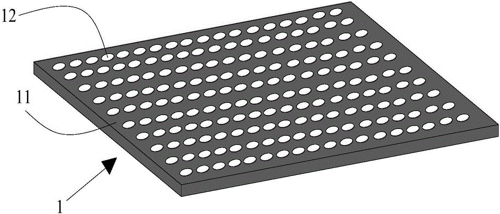
The invention discloses a manufacturing method of a thin film transistor. The manufacturing method comprises the steps that S1, filling material is filled in the holes of a porous substrate so as to acquire a bearing substrate; S2, a flexible film layer is prepared on the bearing substrate; S3, the filling material is removed; S4, an organic light-emitting diode is prepared on the flexible film layer; and S5, the porous substrate is removed so as to acquire the thin film transistor. According to the manufacturing method of the thin film transistor, bubbles generated in the OLED preparation process can be released due to existence of micropores based on the porous substrate having a micropore structure so that the illumination effect of the bubbles on the Array manufacturing process and damage of a vapor plating metal mask plate can be avoided, and the step of removing a sacrificial layer through laser irradiation and the heating step of the conventional manufacturing method can also be omitted. The invention also discloses the porous substrate used by the manufacturing method and the manufacturing method thereof. The porous substrate has no damage after use and can be repeatedly used so that pollution and waste can be reduced and the manufacturing cost of the thin film transistor can be reduced.

Description

technical field [0001] The invention belongs to the technical field of semiconductors, and in particular relates to a porous substrate and a manufacturing method thereof, as well as a method for manufacturing a thin film transistor using the porous substrate. Background technique [0002] At present, the preparation method of flexible OLED devices usually uses a glass substrate as a carrier, and goes through the following main steps: (1) coating a layer of special adhesive on the surface of the glass substrate, or depositing a layer of inorganic substances as a sacrificial layer; (2) The sacrificial layer is coated with polymer monomers, polymers or a mixed solution of monomers and prepolymers, and the monomers are polymerized into a flexible film layer by baking and other processes; (3) Depositing a water-oxygen barrier on the surface of the flexible film layer (4) Perform Array manufacturing process, evaporation and packaging process to complete the preparation of flexible...

Claims


Application Information

Patent Timeline
Patent Type & Authority Applications(China)
IPC IPC(8): H01L21/336H01L21/77H01L27/02
CPCH01L21/77H01L27/02H01L29/66742H01L27/1218H01L27/1266H10K71/80H10K2102/311H10K71/00H10K59/1213H10K59/1201
Inventor 唐凡
Owner WUHAN CHINA STAR OPTOELECTRONICS TECH CO LTD
Learn More