Ammonia process SCR-SNCR coupling flue gas denitrification reactor

A denitrification reactor and flue gas technology, applied in the direction of gas treatment, separation methods, chemical instruments and methods, etc., can solve the problems of non-uniform injection of ammonia, low flue gas efficiency, poor sealing, etc., to achieve thorough denitrification reaction, improve Effects of Processing Efficiency and Effectiveness

Pending Publication Date: 2017-05-31
江苏诺伊拓环保工程有限公司
View PDF13 Cites 5 Cited by
  • Summary
  • Abstract
  • Description
  • Claims
  • Application Information

AI Technical Summary

Problems solved by technology

[0004] The efficiency of flue gas treated by SNCR or SCR alone is low, and there are still some nitrogen oxides in the released flue gas, so the treatment is not thorough, and the main disadvantage of the existing denitrification reactor is that ammonia cannot be uniformly injected into the denitrification body Internally, it affects the efficiency and effect of the reduction reaction and whether the reduction reaction is complete, and the sealing between the ammonia addition system and the denitrification body is poor, resulting in some nitrogen oxides escaping during the ammonia addition process; in addition, the current Some SCR reaction sections must use a catalyst, but the performance of the catalyst module will decline after a period of use, and it needs to be repaired and replaced in time, but the existing structure cannot meet the purpose of convenient maintenance

Method used


Image

  • Ammonia process SCR-SNCR coupling flue gas denitrification reactor
  • Ammonia process SCR-SNCR coupling flue gas denitrification reactor
  • Ammonia process SCR-SNCR coupling flue gas denitrification reactor

Examples


Embodiment Construction

[0028] In order to enable those skilled in the art to better understand the technical solution of the present invention, the technical solution of the present invention will be further described below in conjunction with the accompanying drawings and embodiments.

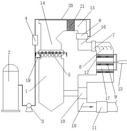
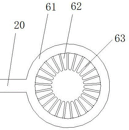
[0029] Refer to attached Figure 1-6 The ammonia-based SCR-SNCR coupled flue gas denitrification reactor includes a denitrification main body, and the denitrification main body includes a furnace 1, a transition section 15, a catalytic section 17, and an air outlet section 18, and the air outlet section 18 is also provided with air preheating A device 10 and a dust collector 11, the air preheater 10 is connected to the furnace 1, and the dust collector 11 is arranged in the gas outlet section 18, and performs dust removal treatment on the pre-discharged and qualified flue gas, so that the discharged The gas is more environmentally friendly and safe. The transition section 15 is also provided with an economizer 21; a...


PUM


Abstract

The invention discloses an ammonia process SCR-SNCR coupling flue gas denitrification reactor which comprises a denitrification body. The denitrification body comprises a hearth, a transition section, a catalyzing section and a gas outlet section, a first reducing section is arranged between the hearth and the transition section, a second reducing section is arranged between the transition section and the catalyzing section, the periphery of the first reducing section is sleeved with an annular ammonia spraying mechanism, and the periphery of the second reducing section is sleeved with an ammonia equivalent injection mechanism. The annular ammonia spraying mechanism and the ammonia equivalent injection mechanism are both connected with an ammonia adding system, and a multi-channel gas mixer is arranged between the second reducing section and the catalyzing section. The catalyzing section is provided with at least one layer of catalyst module. The SCR-SNCR reactor is simple in overall structure, reasonable in design and low in cost, nitric oxide treatment efficiency is greatly improved, ammonia spraying operation is more uniform and comprehensive, a reducer and nitric oxide can be mixed more fully for reacting, reaction efficiency is high, the effect is good, and the reactor is good in airtightness, more environmentally friendly and safer.

Description

technical field [0001] The invention relates to the technical field of environmental protection equipment, in particular to an ammonia method SCR-SNCR coupled flue gas denitrification reactor. Background technique [0002] At present, the SCR process is mainly divided into two types: ammonia-based SCR and urea-based SCR. X The reduction function, under the action of the catalyst, NO X (mainly NO) reduced to N which has little effect on the atmosphere 2 And water, the reducing agent is NH3, in the chemical industry, power plants and other industries will produce more flue gas, and the flue gas contains more nitrogen oxides, if the nitrogen oxides in the flue gas are not treated in time, it will Cause respiratory diseases such as bronchi and emphysema, damage plants, easily form acid rain, acid mist and other major pollutants, easily interact with hydrocarbons to form photochemical smog, and nitrogen oxides also have certain damage to the ozone layer, so in Flue gas must be...

Claims


Application Information

Patent Timeline
Patent Type & Authority Applications(China)
IPC IPC(8): B01D53/86B01D53/76B01D53/56
CPCB01D53/56B01D53/76B01D53/8625B01D53/8631B01D2258/0283B01D2251/2062
Inventor 张兆勇
Owner 江苏诺伊拓环保工程有限公司
Why Eureka
Try Eureka