Low-cost fire extinguisher plastic valve and preparation method thereof
A fire extinguisher, low-cost technology, applied in fire rescue and other directions, can solve the problems of loss of sealing performance of fire extinguisher valves, high production cost, complex structure, etc., and achieve the effects of increasing market competitiveness, good dimensional stability, and improving mechanical properties.
- Summary
- Abstract
- Description
- Claims
- Application Information
AI Technical Summary
Problems solved by technology
Method used
Image

Examples
Embodiment 1
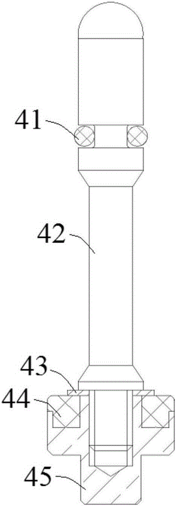
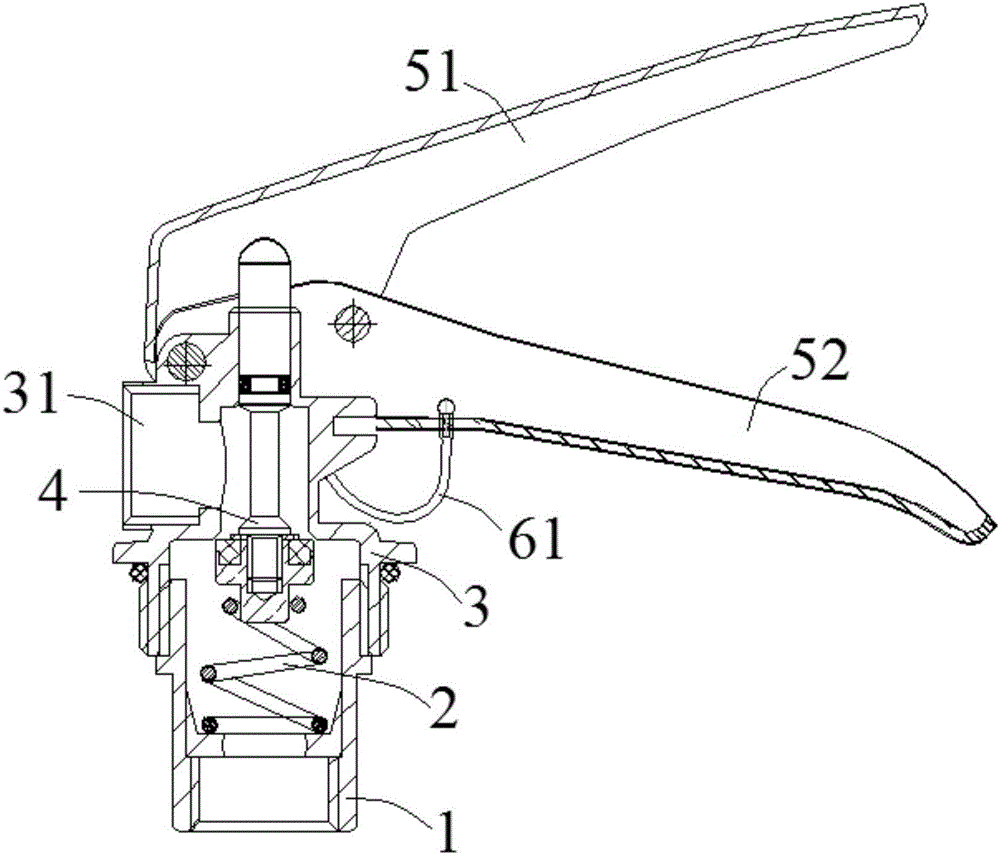
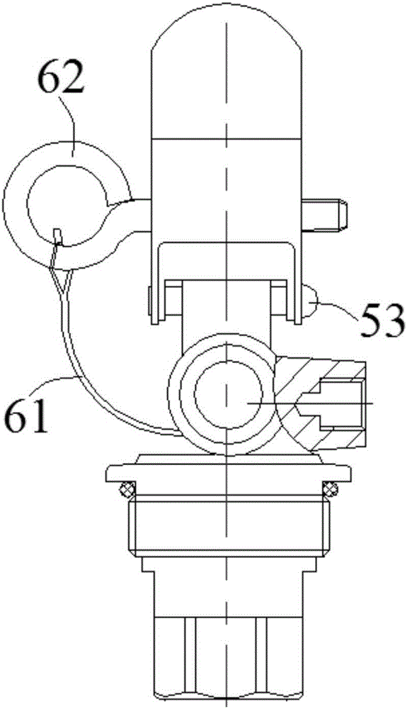
[0041] combine figure 2 , image 3 and Figure 4 , the traditional fire extinguisher valve mainly includes a standpipe seat 1, a spring 2, a valve body 3, a push rod assembly 4, a pressing handle 51 and a carrying handle 52. The valve body 3 is closed and connected with the storage bottle of the fire extinguisher through the standpipe seat 1 , and is provided with a side channel 31 , an upper channel 32 and a lower channel 33 . The valve body 3 is provided with a ejector rod assembly 4, the lower part of the ejector rod assembly 4 is provided with a spring 2, and the upper part is pressed against the pressure handle 51, and the ejector rod assembly 4 passes through the upper passage 32 and the lower passage 33 of the valve body 3 to be used for To realize the sealed filling of the fire extinguishing agent, the press handle 51 and the carrying handle 52 are connected axially by the rivet 53, and a safety pin 62 is also arranged between the pressing handle 51 and the carrying ...
Embodiment 2
[0057] A low-cost fire extinguisher plastic valve in this embodiment is basically the same as in Embodiment 1, except that the nylon composite material used in this embodiment includes the following components:
[0058]
[0059] In this embodiment, the preparation process of the fire extinguisher valve is as follows:
[0060] Step 1. Mix 35 parts of nylon 66 slices, 30 parts of long glass fiber, 1 part of silicon carbide, 1 part of talcum powder and 0.5 part of mica powder under stirring conditions;
[0061] Step 2. Ejector injection molding: Put the mixed raw materials into the feed port of the injection molding machine, and after melting, quickly inject them into the ejector cavity at high pressure with the help of the thrust of the screw; the screw speed of the injection molding machine is 80rpm; the length of the screw of the injection molding machine The diameter ratio is 22. The temperature of the feeding section of the injection molding machine is controlled at 290°...
Embodiment 3
[0066] A low-cost fire extinguisher plastic valve in this embodiment is basically the same as in Embodiment 1, except that the nylon composite material used in this embodiment includes the following components:
[0067]
[0068] The preparation process of the fire extinguisher valve in the present embodiment is as follows:
[0069] Step 1. Mix 38 parts of nylon 66 slices, 28 parts of long glass fibers, 1.5 parts of silicon carbide, 0.6 parts of talcum powder and 0.6 parts of mica powder under stirring conditions;
[0070] Step 2. Put the mixed raw materials into the feeding port of the injection molding machine, and inject them into the mold cavity quickly with the thrust of the screw at high pressure after melting; the screw speed of the injection molding machine is 90rpm; the length-to-diameter ratio of the screw of the injection molding machine is 20. The temperature of the feeding section of the injection molding machine is controlled at 295°C; the temperature of the co...
PUM
 Abstract
Description
Claims
Application Information