Integrated clutch axle hub transmission device

A technology of clutch shaft and transmission device, which is applied in the field of mechanical transmission, can solve the problems of slow response, large impact, and high labor intensity of operators, and achieve the effect of large bearing torque, multiple transmission paths, and compact structure

Inactive Publication Date: 2017-05-31
贵州凯星液力传动机械有限公司
View PDF5 Cites 8 Cited by
  • Summary
  • Abstract
  • Description
  • Claims
  • Application Information

AI Technical Summary

Problems solved by technology

[0003] The purpose of the present invention is to provide an integral clutch shaft-hub transmission device to solve the problems of slow response, large impact, and high labor intensity of the operator when shifting gears in existing mechanical gear transmissions.

Method used


Image

  • Integrated clutch axle hub transmission device
  • Integrated clutch axle hub transmission device

Examples


Embodiment

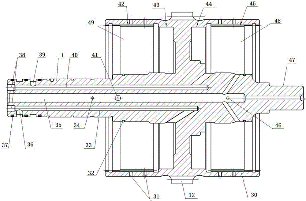
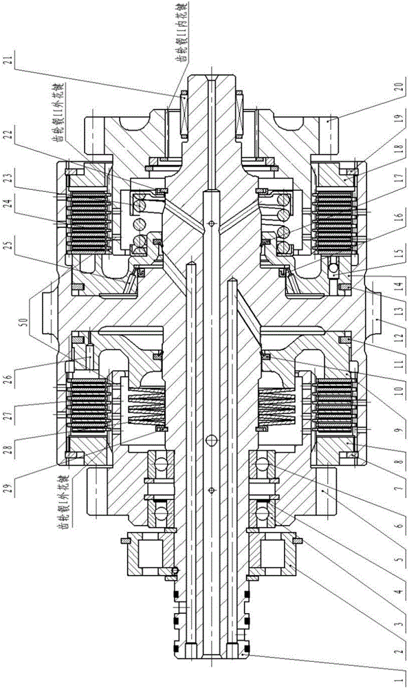
[0036] By engaging or disengaging the clutch A24 and the clutch B27, changing the transmission condition can make the integral clutch shaft-hub transmission device realize different power transmission:

[0037] When the clutch B27 is engaged and the clutch A24 is disconnected, the device can transmit power by the gear hub A5 and the external meshing gear 12;

[0038] When the clutch A24 is engaged and the clutch B27 is disconnected, the device can transmit power through the gear hub B20, the internal spline B45 and the external meshing gear 12;

[0039] When both the clutch A24 and the clutch B27 are engaged, the device can transmit power by the gear hub A5, the gear hub B20, the internal spline B45 and the external gear 12;

[0040] When both the clutch A24 and the clutch B27 are disconnected, the device can transmit power through the external meshing gear 12 .

[0041] The engagement and disengagement process of clutch B27 is as follows:

[0042] When there is no oil in th...


PUM


Abstract

The invention discloses an integrated clutch axle hub transmission device which comprises an external meshing gear, a spindle, a clutch, a bearing, a piston and a return spring. The power transmission path of a transmission axle hub can be changed by engagement and disengagement of the clutch according to the requirement of an electric control hydraulic system to implement different gears. The external meshing gear, a clutch hub and a transmission shaft are integrated by an integrated clutch axle hub to form integrated parts, deformation caused by welding and the like is avoided, transmission stability cannot be affected, the axle hub is provided with a clutch oil inlet channel, a friction pair and a bearing lubricating and cooling oil channel, and the clutch is disengaged by the piston and the return spring. The device has the advantages of compact structure, working stability, high bearing torque, easiness in implementing automatic control and the like.

Description

technical field [0001] The invention relates to the technical field of mechanical transmission, in particular to an integral clutch hub transmission device. Background technique [0002] The traditional mechanical gear box adopts fixed shaft gear transmission, which is widely used in construction machinery due to its simple structure, high transmission efficiency, large load capacity, reliable operation, and low cost. However, when shifting gears in a traditional mechanical gear transmission, it is necessary to disengage the clutch connected to the power source and the transmission, and adjust the axial position of the gear through the shift fork, so that the other gear meshes with the transmission wheel, and then changes the transmission ratio to achieve The purpose of gear shifting; this gear shifting method has slow response and large impact, and because the operator needs to step on the clutch, the labor intensity of the operator is increased under the working conditions...

Claims


Application Information

Patent Timeline
Patent Type & Authority Applications(China)
IPC IPC(8): F16D25/10F16D25/0638F16D25/12F16H57/00F16H57/04
CPCF16D25/0638F16D25/10F16D25/12F16D25/123F16H57/0006F16H57/0018F16H57/043F16H57/0471F16H57/0473F16D2300/08F16D2300/12
Inventor 蒋辰希李世鹏张承元占单林
Owner 贵州凯星液力传动机械有限公司
Why Eureka
Try Eureka