Micro evaporator, oscillator-integrated micro evaporator structure and frequency correction method thereof

An evaporator and oscillator technology, applied in the sensing field, can solve the problems of inability to achieve oscillator frequency calibration and high oscillator frequency dispersion, and achieve the effects of small heat capacity, improved accuracy, and less heat dissipation

Inactive Publication Date: 2017-06-06
SHANGHAI INST OF MICROSYSTEM & INFORMATION TECH CHINESE ACAD OF SCI
View PDF4 Cites 2 Cited by
  • Summary
  • Abstract
  • Description
  • Claims
  • Application Information

AI Technical Summary

Problems solved by technology

[0007] The present invention aims at the above-mentioned deficiencies in the prior art. The purpose of the present invention is to provide a micro-evaporator, an oscillator integrated micro-evaporator structure and a frequency correction method thereof, which are used to solve the frequency dispersion of the oscillator in the prior art. The problem of high reliability, and because the oscillator is vacuum packaged through the wafer-level packaging process, it is difficult to fine-tune the structure of the resonant unit packaged in the vacuum cavity, and the frequency calibration of the oscillator cannot be achieved

Method used


Image

  • Micro evaporator, oscillator-integrated micro evaporator structure and frequency correction method thereof
  • Micro evaporator, oscillator-integrated micro evaporator structure and frequency correction method thereof
  • Micro evaporator, oscillator-integrated micro evaporator structure and frequency correction method thereof

Examples


Embodiment 1

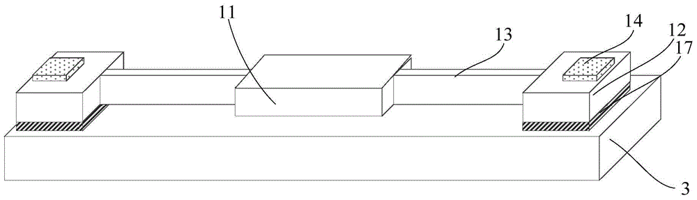
[0089] see figure 1 , the present invention provides a kind of micro-evaporator, described micro-evaporator comprises: micro-evaporation table 11, anchor point, support beam and metal electrode; and the metal electrodes are respectively defined as the first anchor point 12, the first support beam 13 and the first metal electrode 14;

[0090] One side of the micro-evaporation table 11 is an evaporation surface; the first anchor point 12 is located on both sides of the micro-evaporation table 11, and is separated from the micro-evaporation table 11 by a certain distance; the first support beam 13 Located between the micro-evaporation table 11 and the first anchor point 12, one end is connected to the micro-evaporation table 11, and the other end is connected to the first anchor point 12; the first support beam 13 Dimensions (ie length, width, height) satisfy the following relationship: Wherein, b, h, L are respectively the width, thickness and length of the support beam, T is...

Embodiment 2

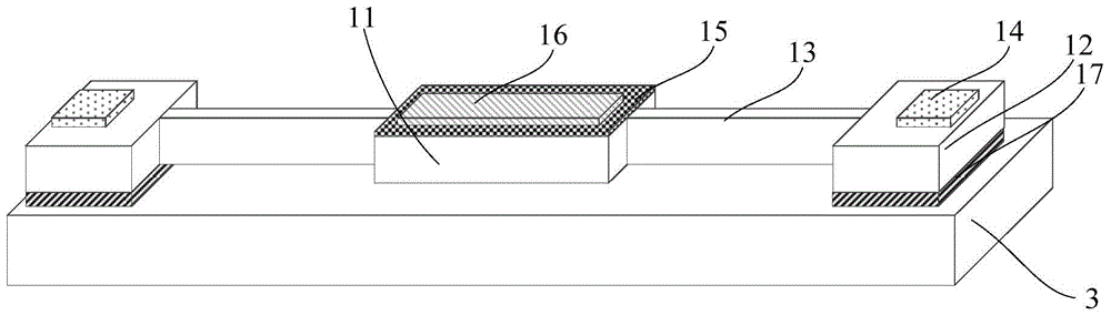
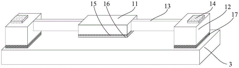
[0098] see Figure 2 to Figure 3 , the present invention also provides a micro-evaporator, the structure of the micro-evaporator is roughly the same as that of the micro-evaporator described in the first embodiment, and the micro-evaporator in the present embodiment is compared with the The difference between the micro-evaporators described in:

[0099] The micro-evaporator also includes an evaporation material 16 , and the evaporation material 16 is located on the evaporation surface of the micro-evaporation table 11 .

[0100] As an example, when the saturated vapor pressure of the evaporating material 16 is greater than 10 -6 The temperature of Torr is lower than the melting point of the micro-evaporation platform 11, and the evaporation material 16 can be selected from metal, semiconductor or insulating materials, such as aluminum, germanium, gold or semiconductor materials such as silicon and germanium. When the micro-evaporator is integrated with the oscillator to revi...

Embodiment 3

[0106] see Figure 4 , the present invention provides an oscillator-integrated micro-evaporator structure, the oscillator-integrated micro-evaporator structure includes the micro-evaporator and the oscillator as described in Embodiment 1;

[0107] The micro-evaporator and the oscillator are jointly sealed in the same vacuum chamber, the micro-evaporator and the oscillator are arranged correspondingly up and down, and the evaporation surface of the micro-evaporation platform 11 in the micro-evaporator faces the oscillator device.

[0108] As an example, the oscillator can be a quartz oscillator, a silicon-based MEMS oscillator, or other oscillators, and there is no limitation on the type and structure of the oscillator, that is, the oscillator Any existing oscillator can be used.

[0109] In this embodiment, taking a bending mode oscillator as an example, the oscillator includes a resonant unit 21, a second support beam 22, a second anchor point 23, and a second metal electro...


PUM


Abstract

The invention provides a micro evaporator, an oscillator-integrated micro evaporator structure and a frequency correction method thereof. The micro evaporator comprises a micro evaporator table, anchor points, supporting beams and metal electrodes, wherein one surface of the micro evaporator table is an evaporation surface; the anchor points are located at two sides of the micro evaporator table, and a certain distance is left with the micro evaporator table; the supporting beams are located between the micro evaporator table and the anchor points, one end of each supporting beam is connected with the micro evaporator table and the other end is connected with the anchor point; the size of the supporting beam meets the following relation as is shown in the specifications; and the metal electrode is located on the surface of the anchor point. The micro evaporator table is connected with the anchor points with the metal electrodes formed on the surfaces through the supporting beams, through adjusting and setting the size of the supporting beam, features of small thermal capacity and little cooling of the supporting beam are realized; as the micro evaporator table and the supporting beam have a small size, needed evaporation temperature can be achieved on the micro evaporator table through applying small power to the surface of the metal electrode; and due to heat insulation of the supporting beam, the temperature rise at the anchor point is little, and the stability of the device is not influenced.

Description

technical field [0001] The invention belongs to the field of sensing technology, in particular to a micro-evaporator, an oscillator integrated micro-evaporator structure and a frequency correction method thereof. Background technique [0002] Oscillators are basic components that provide clock frequencies in digital electronic systems and are used in almost all electronic systems. In modern communication systems, due to limited frequency resources and numerous users, extremely high requirements are placed on the accuracy of the oscillator frequency. GSM mobile phones require the frequency accuracy of the oscillator to be within ±2.5ppm, while mobile base stations require the stability of the oscillator to be within ±0.05ppm. [0003] For a long time, quartz crystal resonators have been the main components for providing clock frequency signals in electronic systems, with stable performance and good temperature characteristics. However, quartz oscillators are difficult to in...

Claims


Application Information

Patent Timeline
Patent Type & Authority Applications(China)
IPC IPC(8): H03B1/02
CPCH03B1/02B81B3/0078B81B2201/0271B81B2203/0109C23C14/24H01L21/02532H01L21/02631H03H3/0077H03H9/02401H03H9/1057H01L21/0242H01L21/02488H01L21/02491H03H9/24
Inventor 杨恒游卫龙张磊王小飞李昕欣
Owner SHANGHAI INST OF MICROSYSTEM & INFORMATION TECH CHINESE ACAD OF SCI
Why Eureka
Try Eureka