Mask and equipment containing mask

A mask and equipment technology, applied in the field of liquid crystal display panel manufacturing process, can solve the problem that the mask affects the efficiency of the machine, and achieve the effect of reducing the type and quantity of use

Inactive Publication Date: 2017-06-13
TCL CHINA STAR OPTOELECTRONICS TECH CO LTD
View PDF3 Cites 3 Cited by
  • Summary
  • Abstract
  • Description
  • Claims
  • Application Information

AI Technical Summary

Problems solved by technology

[0005] Aiming at the problem that there are many kinds of masks used for curing frame sealing glue in the prior art, and the machine efficiency is affected when the mask is replaced, the present invention proposes a mask, and further proposes a device containing the mask

Method used


Image

  • Mask and equipment containing mask
  • Mask and equipment containing mask
  • Mask and equipment containing mask

Examples


Embodiment 1

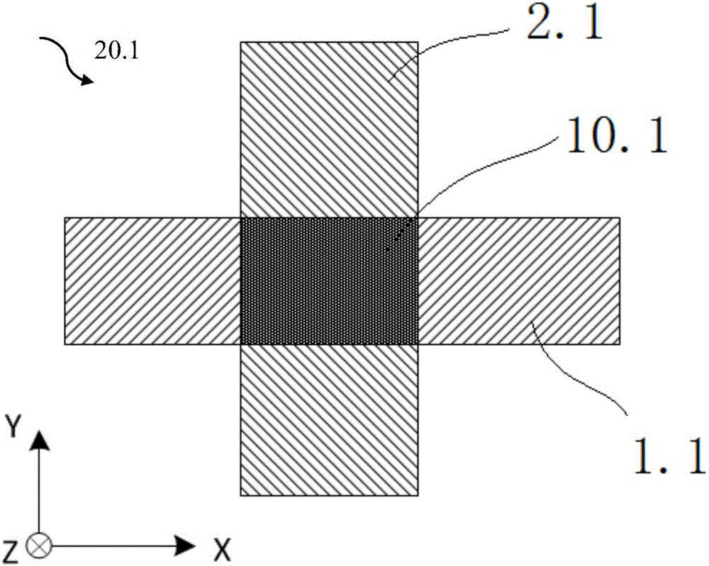
[0037] figure 2 It is a schematic diagram of the mask 20.1 of the first embodiment of the present invention, the mask 20.1 includes an X polarizer 1.1 and a Y polarizer 2.1, and the polarization direction of the X polarizer 1.1 is perpendicular to the polarization direction of the Y polarizer 2.1, and the X polarizer The X plane to which sheet 1.1 belongs is parallel to the Y plane to which Y polarizer 2.1 belongs. The angle between the direction and the Y direction is greater than 0 degrees, and the normal direction of the X plane or the Y plane is defined as the Z direction. When observing along the Z direction, the X polarizer 1.1 overlaps the Y polarizer 2.1, and the X polarizer is set The overlapping area of ​​sheet 1.1 and Y polarizing sheet 2.1 is the first overlapping area 10.1. Since X polarizing sheet 1.1 and Y polarizing sheet 2.1 have the same polarization direction, the polarized light passing through X polarizing sheet 1.1 cannot pass through Y polarizing sheet ...

Embodiment 2

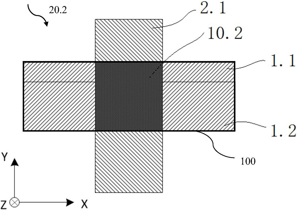
[0039] On the basis of the first embodiment, when the width of the liquid crystal region along the Y direction on the substrate of the sealant to be cured is greater than the width of the X polarizer 1.1 along the Y direction, multiple X polarizers can be arranged along the Y direction as required. polarizer. Such as image 3 It is a schematic diagram of the mask 20.2 of the second embodiment. At this time, the width of the liquid crystal region 10.2 on the substrate along the X direction matches the width of a Y polarizer 2.1 along the X direction, but the width of the liquid crystal region 10.2 along the Y direction The width is greater than the width of X polarizer 1.1 along the Y direction, but smaller than the width of the two X polarizers along the Y direction, so two X polarizers are set in the mask 20.2, namely X polarizer 1.1 and X polarizer 1.2.

[0040] Such as image 3 , the X polarizer 1.1 and the X polarizer 1.2 are arranged in parallel in different planes, the...

Embodiment 3

[0044] On the basis of the second embodiment, when the width of the liquid crystal region along the X direction of the substrate of the sealant to be cured is greater than the width of the Y polarizer 2.1 along the X direction, multiple Y polarizers can be set along the X direction as required piece. Such as image 3 It is a schematic diagram of the mask 20.3 of the third embodiment. At this time, the width of the liquid crystal region 10.3 on the substrate along the X direction is greater than the width of the Y polarizer 2.1 along the X direction, but smaller than the width of the two Y polarizers along the X direction , so two Y polarizers are set in the mask 20.3, that is, Y polarizer 2.1 and Y polarizer 2.2.

[0045] Such as Figure 4 , the Y polarizer 2.1 and the Y polarizer 2.2 are arranged in parallel in different planes, the Y polarizer 2.1 and the Y polarizer 2.2 are respectively arranged along the Y direction in the plane, and observed along the Z direction, the Y...


PUM


Abstract

The invention provides a mask, which aims at solving the problems of multiple mask types and manual replacement in the existing sealant curing technique. The mask is formed by overlapping an X polarizer and a Y polarizer of which the polarization directions are mutually vertical, so as to obtain an overlapping area; the light rays are not allowed to penetrate through the overlapping area, but are allowed to penetrate through the areas outside the overlapping area. The mask has the advantages that by reasonably arranging the number of the X polarizer and the number of the Y polarizer, the overlapping area matched with a liquid crystal area is obtained; the liquid crystal area is completely covered by the overlapping area, and exposure light rays only cure the sealant outside the liquid crystal area; the mask is suitable for curing the sealants with different sizes, and the additional manufacturing of the sealant curing mask is not needed, so that the type and number of masks in the manufacturing process are reduced. The invention also provides equipment containing the mask, so that the manual operation is replaced, and the production efficiency is improved.

Description

technical field [0001] The invention relates to the field of liquid crystal display panel manufacturing process, in particular to a mask used in the liquid crystal display panel manufacturing process and equipment containing the mask. Background technique [0002] The liquid crystal display panel manufacturing process mainly includes coating, exposure, development, etching, and stripping processes. The so-called exposure is to transfer the circuit graphics required to control the liquid crystal molecules and the pixel graphics for displaying images drawn on the mask onto the glass substrate. superior. In this process, the mask plays a crucial role, so the type and process of the mask have a great impact on the manufacturing process of the liquid crystal display panel. [0003] Use selected images, graphics or objects to block the processed image (all or part) to control the area or process of image processing. The specific image or object used for coverage is called a mask ...

Claims


Application Information

Patent Timeline
Patent Type & Authority Applications(China)
IPC IPC(8): G03F1/50G03F7/20G02F1/13
CPCG03F1/50G02F1/1303G03F7/20
Inventor 王松张瑞军李培宏
Owner TCL CHINA STAR OPTOELECTRONICS TECH CO LTD
Why Eureka
Try Eureka