Shifting register unit, grid electrode drive circuit and drive method

A shift register, driving method technology, applied in static memory, digital memory information, instruments, etc., can solve the problems of high circuit power consumption, lowering the output level, thin film transistor threshold voltage drift, etc., and achieves simple structure, The effect of low noise and low power consumption

Inactive Publication Date: 2017-06-13
BOE TECH GRP CO LTD +1
View PDF8 Cites 32 Cited by
  • Summary
  • Abstract
  • Description
  • Claims
  • Application Information

AI Technical Summary

Problems solved by technology

[0003] The design of the existing gate drive circuit is relatively complicated, usually using a lot of clock signals and a lot of thin film transistors, resulting in high power consumption and high noise in the circuit
In addition, in the existing gate drive circuit, the output terminal of the circuit keeps low level after outputting a high level in one frame scanning, so the pull-down node must always maintain a high positive level to make the thin film transistor connected to the output terminal Turning on, thereby pulling down the output terminal level, the continuous high positive level of the gate of such a thin film transistor is likely to cause the threshold voltage drift of the thin film transistor, which seriously affects the normal display of the liquid crystal panel

Method used


Image

  • Shifting register unit, grid electrode drive circuit and drive method
  • Shifting register unit, grid electrode drive circuit and drive method
  • Shifting register unit, grid electrode drive circuit and drive method

Examples


Embodiment Construction

[0028] The technical solutions in the embodiments of the present disclosure will be clearly and completely described below in conjunction with the accompanying drawings. Apparently, the described embodiments are only some of the embodiments of the present disclosure, rather than all of them. Based on the embodiments of the present disclosure, all other embodiments obtained by persons of ordinary skill in the art without making creative efforts also fall within the protection scope of the present disclosure.

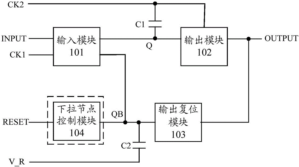
[0029] figure 1 is a block diagram of a shift register cell according to an embodiment of the disclosure. Such as figure 1 As shown, the shift register unit includes: an input module 101, connected between the input terminal INPUT, the first clock signal terminal CK1, the pull-up node Q and the pull-down node QB, configured as an input signal connected to the input terminal INPUT Under the control of the first clock signal connected to the first clock signal terminal CK...


PUM


Abstract

The invention discloses a shifting register unit, a grid electrode drive circuit comprising the shifting register unit and a drive method used for the shifting register unit. The shifting register unit comprises an input module, an output module, an output return module and a first capacitor, wherein the first capacitor is connected between an upper pulling node and a second clock signal end, and is configured to keep high electrical level of the upper pulling node by a second clock signal accessed through a second clock signal end. The shifting register unit further comprises a second capacitor which is connected between a lower pulling node and a first voltage input end, and is configured to reduce electric level of the lower pulling node by reverse bias voltage accessed through the first voltage input end within blanking time after one-frame scanning is ended. The shifting register unit is simple in structure, has full-oscillation-amplitude output, is low in power loss, is small in noise, and restores drifting of threshold voltage of a film transistor connected with an output end, so that normal display of a liquid crystal panel is kept.

Description

technical field [0001] The present disclosure relates to the field of display technology, and in particular to a shift register unit, a gate drive circuit including the shift register unit, and a driving method applied to the shift register unit. Background technique [0002] In the field of display technology, a liquid crystal display is a commonly used flat-panel display at present, and a pixel array of a liquid crystal display usually includes multiple rows of gate lines and multiple columns of data lines interlaced. Wherein, the driving of the gate lines can be completed by connecting an integrated circuit outside the liquid crystal panel. In recent years, with the continuous improvement of the amorphous silicon thin film technology, it is also possible to directly fabricate the gate driver circuit on the thin film transistor array substrate to form a GOA (Gate driver On Array) circuit to drive the gate lines. Since the GOA circuit can be directly fabricated around the ...

Claims


Application Information

Patent Timeline
Patent Type & Authority Applications(China)
IPC IPC(8): G09G3/36G11C19/28
CPCG09G3/36G11C19/28G09G2310/0286G09G3/3677G09G2320/043G09G2310/0289G09G2310/0267
Inventor 李蒙李永谦徐攀张淼
Owner BOE TECH GRP CO LTD
Why Eureka
Try Eureka