Optical fiber buncher drawing method

A beam concentrator and manufacturing method technology, which is applied in the directions of beam optical fibers, manufacturing tools, glass manufacturing equipment, etc., can solve the problems of difficulty in selecting the taper drawing speed and flame moving speed, neat arrangement of optical fibers, and difficulty in close arrangement, etc. Complete protection, complete stripping, avoiding surface damage and fiber breakage

Inactive Publication Date: 2017-06-16
NO 34 RES INST OF CHINA ELECTRONICS TECH GRP +2
View PDF4 Cites 0 Cited by
  • Summary
  • Abstract
  • Description
  • Claims
  • Application Information

AI Technical Summary

Problems solved by technology

[0007] However, it is difficult to achieve such a tight arrangement in the existing drawing method of the bundler, especially when the number of cores is large, it is impossible to ensure that the multiple optical fibers are arranged neatly according to the above rules before drawing, although experienced technicians A lot of time is spent on densely arranging optical fibers, but the yield is still extremely low. The parallelism between cores is determined by on-site operation, and the repeatability is extremely low.
[0008] When the insertion loss index of the drawn optical fiber bundler does not meet the requirements, it is only possible to try drawing again by changing the speed of the taper and the speed of the flame. However, there is too much room for adjustment of the parameters related to the speed of the taper and the speed of the flame. paired parameters greater than 10 6 , it is too time-consuming to test, and it is difficult to select the appropriate taper speed and flame moving speed, so as to realize the fiber bundler that meets the insertion loss index

Method used


Image

  • Optical fiber buncher drawing method
  • Optical fiber buncher drawing method
  • Optical fiber buncher drawing method

Examples


Embodiment Construction

[0038] The embodiment of the drawing method of the optical fiber bundler includes the following working steps:

[0039] Ⅰ. Optical fiber coating removal

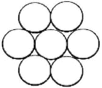
[0040] In this example, a 7-core fiber bundler is to be prepared.

[0041] Immerse one end of 7 optical fibers with a length of 70 mm in concentrated sulfuric acid for 30 minutes, take out the optical fiber whose coating layer has been stripped, rinse it with clean water, wipe the bare optical fiber with ethanol and acetone solution for 5 times, and observe each optical fiber under a microscope. Take a bare fiber and make sure that the handling process did not cause damage.

[0042] Ⅱ. Quartz tube sleeve fiber

[0043] Select a glassy pure silica tube with a length of 50 mm, the inner diameter of which is just enough for 7 bare fiber bundles to pass through smoothly, that is, the inner diameter is equal to that of 7 bare fiber bundles, the outer diameter is 0.4 mm, and the wall thickness of the quartz tube is 0.2 mm;

[0...


PUM

PropertyMeasurementUnit
lengthaaaaaaaaaa
thicknessaaaaaaaaaa
lengthaaaaaaaaaa

Abstract

The invention provides an optical fiber buncher drawing method comprising the following steps that a bare optical fiber bundle of which the optical fiber coating layer is removed penetrates into a quartz tube with the two ends arranged outside the ports of the quartz tube, wherein the internal diameter of the quartz tube just allows penetration of the bare optical fiber bundle; and the two ends of the quartz tube in which the optical fiber bundle penetrates are arranged in a tapering clamp to be fixed, and the tapered quartz tube and the internal optical fiber bundle form an integrated optical fiber buncher. According to the method, the flame jet tube height is adjusted to change the heating temperature of the quartz tube so as to reduce the inserting loss. A height adjusting frame of the spiral structure is additionally arranged below the flame jet tube so as to quantitatively adjust the height in a grading way. The optimal flame jet tube height of the buncher of the qualified drawing inserting loss can be obtained through multiple types of drawing and adjustment. The horn mouth of one end of the quartz tube effectively protects the optical fiber bundle. The optical fiber bundle can be perfectly constrained by the quartz tube to be optimally and closely arranged so that the duty ratio and the inter-core parallelism can be enhanced and the efficiency can be substantially enhanced; and the heating temperature of the quartz tube is progressively and accurately controlled so that the optical fiber buncher of the qualified inserting loss is ensured to be obtained through tapering and the adjustment time can be shortened.

Description

technical field [0001] The invention relates to the technical field of drawing an optical fiber bundler, in particular to a method for drawing an optical fiber bundler. A quartz tube sleeve restricts the optical fibers to be closely arranged outside the fiber bundle. Background technique [0002] In the practical application of laser inertial confinement fusion, high-energy laser system and other fields, it is necessary to achieve high energy output, and at the same time require high electro-optical and optical-optical conversion efficiency. The optical fiber amplification network (FAN) can realize the single pulse energy output of the laser fusion ignition device above megajoules, and has the characteristics of high wall insertion efficiency and flexible optical path. However, to achieve such a high single-pulse energy output, tens of millions of large-mode-field-gain fibers need to be used, and at the same time, it needs to be based on a fiber bundler to realize the bundle...

Claims


Application Information

Patent Timeline
Patent Type & Authority Applications(China)
IPC IPC(8): G02B6/04C03B37/028
CPCG02B6/04C03B37/028
Inventor 吴国锋刘志强童章伟阳华岳耀笠李沼云张昕赵灏刘霄海
Owner NO 34 RES INST OF CHINA ELECTRONICS TECH GRP
Why Eureka
Try Eureka