Underground power drilling bit device

A drill bit and power technology, which is applied in the direction of the driving device, drill bit, and drill pipe for drilling in the wellbore, can solve the problems of low drilling efficiency, large pressure loss, and slow drilling speed, and achieve efficient and fast drilling. The effect of sufficient pressure and large drilling depth

Active Publication Date: 2017-06-20
CHINA UNIV OF PETROLEUM (BEIJING)
View PDF6 Cites 3 Cited by
  • Summary
  • Abstract
  • Description
  • Claims
  • Application Information

AI Technical Summary

Problems solved by technology

[0003] In the process of drilling and exploration of deep wells and ultra-deep wells with traditional drill bit devices, there is a large loss in the process of surface energy being transmitted from the ground to the bottom of the well, resulting in insufficient bottom-hole pressure, slow drilling speed, and low drilling efficiency
If the pressure of surface energy is increased, although the energy transmitted to the bottom of the well will be increased, excessive pressure will cause the drill pipe of the drill bit device to yield, deform or even collapse.
In addition, the liquid flowback system in the traditional drill bit device is for safety reasons, the ground cannot provide too high pump pressure, and the drilling fluid in deep and ultra-deep wells loses a lot of pressure along the way, resulting in insufficient hydraulic energy at the bottom of the well , the rock-carrying efficiency is not high
[0004] At the same time, deep oil and gas resources are mostly buried in basins and mountainous areas. The power supply for drilling and exploration depends on the power grid erected by power plants, and the cost of electricity consumption is relatively high. However, traditional power plants use fossil energy to generate electricity, and the energy utilization rate is low. Emit toxic and harmful particles and greenhouse gases, seriously pollute the environment and aggravate the greenhouse effect
In addition, due to the high hardness and poor drillability of rocks in deep formations, traditional water jet drilling has low drilling efficiency, long cycle time and high cost in deep hard formations.

Method used


Image

  • Underground power drilling bit device
  • Underground power drilling bit device
  • Underground power drilling bit device

Examples


Embodiment Construction

[0055] The following will clearly and completely describe the technical solutions in the embodiments of the present invention with reference to the accompanying drawings in the embodiments of the present invention. Obviously, the described embodiments are only some, not all, embodiments of the present invention. Based on the embodiments of the present invention, all other embodiments obtained by persons of ordinary skill in the art without making creative efforts belong to the protection scope of the present invention.

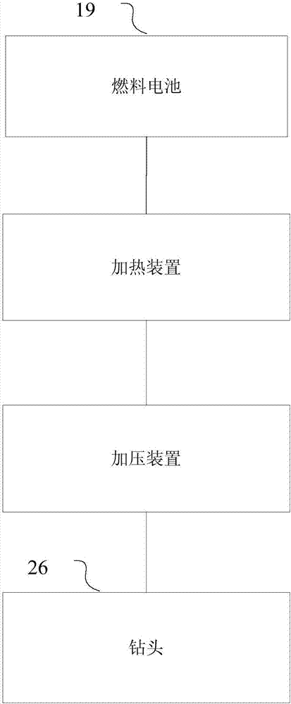
[0056] The principle and spirit of the present invention will be explained in detail below with reference to several representative embodiments of the present invention. Firstly, the technical theory of the present invention is introduced. Combining the high-pressure water jet method and the rock thermal cracking rock breaking method, the present invention proposes a new high-temperature jet high-efficiency rock-breaking scheme. The high-pressure water jet sch...


PUM


Abstract

The invention provides an underground power drilling bit device, and relates to the technical field of energy drilling. The underground power drilling bit device includes fuel batteries, a heating device, a pressurization device, and a drilling bit; the fuel batteries are used for receiving the hydrogen and the oxygen which are conveyed by an external portion, and allowing the hydrogen and the oxygen to perform reaction so as to release heat and electric energy; the heating device is used for absorbing the heat to perform heating on a drilling fluid, and forming supercritical drilling fluid to accelerate drilling at a specific temperature and pressure; and the pressurization device is used for pressurizing the gasified drilling fluid under the action of the electric energy, and ejecting the pressurized drilling fluid via the drilling bit so as to perform jet drilling. The underground power drilling bit device can achieve high-efficient and rapid drilling, can reach a greater drilling depth, and can meet the demand of drilling currently.

Description

technical field [0001] The present invention relates to the technical field of energy drilling, in particular to petroleum engineering drilling technology, and specifically relates to a downhole dynamic drill bit device. Background technique [0002] With the exploration and development of shallow oil and gas resources getting higher and higher, deep oil and gas resources have become an important field for the strategic succession of oil and gas resources in my country. About 40% of my country's remaining oil and gas resources are located in deep formations (≥4500m), and the exploration and development of deep oil and gas resources has become a major demand for my country's oil and gas development. Therefore, how to exploit deep oil and gas resources is the current research focus. [0003] In the process of drilling and exploration of deep wells and ultra-deep wells with traditional drill bit devices, there is a large loss in the process of surface energy being transmitted ...

Claims


Application Information

Patent Timeline
Patent Type & Authority Applications(China)
IPC IPC(8): E21B7/18E21B10/08E21B10/60E21B17/10E21B4/04
CPCE21B4/04E21B7/18E21B10/08E21B10/60E21B17/1028
Inventor 宋先知刘昱李根生黄中伟郑睿田守嶒史怀忠王海柱
Owner CHINA UNIV OF PETROLEUM (BEIJING)
Why Eureka
Try Eureka