Garbage incinerator sludge direct mixing blending combustion method and system

A waste incinerator and sludge technology, applied in the direction of combustion method, incinerator, combustion type, etc., can solve the problems of reduced power generation, lower calorific value, and inability to catch fire, etc., to achieve fast processing speed and improved ecological environment.

Inactive Publication Date: 2017-06-20
北京高安屯垃圾焚烧有限公司
View PDF5 Cites 8 Cited by
  • Summary
  • Abstract
  • Description
  • Claims
  • Application Information

AI Technical Summary

Problems solved by technology

At present, less than 50% of the sludge has been disposed of as compost and building materials, and the rest of the sludge is only temporarily piled up, lacking effective final disposal
Therefore, if the proportion of sludge mixed is too high, the water content of the mixed fuel of sludge and domestic waste will increase, the calorific value will decrease, and the power generation per unit weight will decrease. If the proportion of mixed incineration is too high, it will even fail to ignite and affect the mixing Combustion operation

Method used


Image

  • Garbage incinerator sludge direct mixing blending combustion method and system
  • Garbage incinerator sludge direct mixing blending combustion method and system
  • Garbage incinerator sludge direct mixing blending combustion method and system

Examples


Embodiment Construction

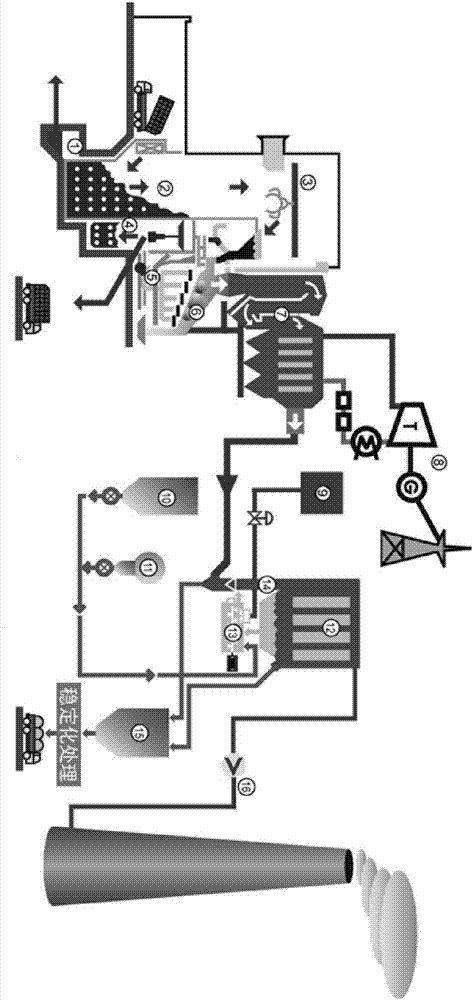
[0069] refer to figure 2 , figure 2 It shows the garbage sludge mixed incineration incineration system of the present invention, which includes: garbage sludge unloading unit, garbage temporary storage mixing and stirring unit, garbage transfer unit, garbage sludge incineration unit, thermal energy conversion unit, power generation unit, Flue gas treatment unit. The collected domestic garbage and sludge are dumped by the garbage (sludge) transport vehicle into the garbage temporary storage mixing unit through the unloading platform. After a certain period of fermentation and dehydration in the temporary storage mixing unit, and fully stirred and mixed evenly, it enters the garbage sludge and mixes it into the furnace transfer unit. The garbage transfer unit is located above the garbage temporary storage mixing unit and the garbage incineration unit. Transfer from the garbage temporary storage mixing unit to the garbage incineration unit. The waste incineration unit is con...


PUM


Abstract

The invention relates to a garbage incinerator sludge direct mixing blending combustion method and system. The garbage incinerator sludge direct mixing blending combustion system comprises an unloading unit, a temporary storage stirring unit, a transferring unit, an incineration unit, a heat energy conversion unit, an electricity generation unit and a smoke treatment unit. The temporary storage stirring unit stores the mixture of sludge and domestic garbage, and the sludge in the mixture accounts for 10-15%. The transferring unit is used for transferring the mixture from the temporary storage unit into the incineration unit, high-temperature smoke generated by the mixture in the incineration unit enters the heat energy conversion unit, the heat energy of the high-temperature smoke enables water in the heat energy conversion unit to from high-temperature and high-pressure steam, and the steam drives the electricity generation unit to generate electricity. Smoke coming from the heat energy conversion unit enters the smoke treatment unit, is subjected to harmless treatment in the smoke treatment unit and then is exhausted into the atmosphere. The garbage incinerator sludge direct mixing blending combustion method and system realize mixed incineration of the sludge and the domestic garbage, clean electricity is produced through combustion waste heat, and the smoke is exhausted in an environmental protection mode after being effectively treated.

Description

technical field [0001] The present application relates to a method and system for directly mixing and blending waste incinerator sludge, which can be widely used in the fields of municipal sludge treatment and waste incineration. Background technique [0002] With the increase of sewage treatment facilities in our country, the improvement of treatment rate and the deepening of treatment degree, the sludge output of sewage treatment plants has increased sharply. Taking Beijing as an example, in 2015, the sludge output in Beijing reached 5,000 tons / day (moisture content 80%). Mud (water content 80%) output will reach 2 million tons. At present, less than 50% of the sludge has been disposed of as compost and building materials, and the rest of the sludge is only temporarily piled up, lacking effective final disposal. Sludge contains pathogens, heavy metals and other toxic and harmful substances. Without effective treatment and disposal, it is very easy to cause secondary poll...

Claims


Application Information

Patent Timeline
Patent Type & Authority Applications(China)
IPC IPC(8): F23G5/00F23G5/04F23G5/44F23G5/46F23J15/02F01D15/10F01K11/02
CPCY02E20/12F23G5/008F01D15/10F01K11/02F23G5/04F23G5/44F23G5/46F23G2201/702F23G2206/203F23J15/006F23J15/02
Inventor 王炳胜雷艳青
Owner 北京高安屯垃圾焚烧有限公司
Why Eureka
Try Eureka