Reactor for purifying organic waste gas under cooperation of plasmas and ultraviolet ray catalysis

A plasma and catalytic purification technology, used in chemical instruments and methods, separation methods, gas treatment, etc., can solve the problems of low processing efficiency, low energy utilization, toxic by-products, etc., to promote organic integration and overall structure. Simple and practical, outstanding effect

Pending Publication Date: 2017-06-27
浙江旭达环保技术有限公司
View PDF10 Cites 4 Cited by
  • Summary
  • Abstract
  • Description
  • Claims
  • Application Information

AI Technical Summary

Problems solved by technology

However, the single photocatalytic technology also faces the limitation of the reactor by the ultraviolet light source, low processing efficiency, low energy utilization rate, low photocatalytic performance, water vapor poisoning the catalytic performance of the catalyst, deactivation of the photocatalyst, and toxic by-products. It is difficult to deal with the disadvantages of high-concentration and large-volume gas

Method used


Image

  • Reactor for purifying organic waste gas under cooperation of plasmas and ultraviolet ray catalysis
  • Reactor for purifying organic waste gas under cooperation of plasmas and ultraviolet ray catalysis

Examples


Embodiment 1

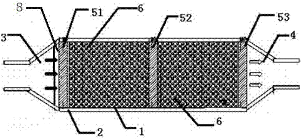
[0024] Such as figure 1 As shown, a reactor for catalytically purifying organic waste gas with plasma and ultraviolet photocatalysis, including a housing 1 and an insulating layer 2, the insulating layer 2 is fixed outside the housing 1, and the housing 1 is provided with two plasma Body discharge unit, air inlet 3, air outlet 4, filter dust removal unit 8, one plasma discharge unit includes stainless steel plate 51, stainless steel plate 52, another plasma discharge unit includes stainless steel plate 52, stainless steel plate 53, two plasma discharge units The bulk discharge unit shares a stainless steel plate 52, the stainless steel plate 52 is connected to high voltage electricity, the stainless steel plate 51, and the stainless steel plate 53 are all connected to the ground, and the filter and dust removal unit 8 is located between the air inlet 3 and the plasma discharge unit. The air port 3 is connected to one end of the filter and dust removal unit 8, and the other end...

Embodiment 2

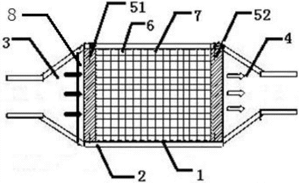
[0031] like figure 2 As shown, a reactor for catalytically purifying organic waste gas with plasma and ultraviolet light, including a shell 1 and an insulating layer 2, the insulating layer 2 is fixed outside the shell 1, and a plasma Discharge unit, air inlet 3, air outlet 4, plasma discharge unit comprises stainless steel plate 51, stainless steel plate 52, stainless steel plate 52 connects high-voltage electricity, stainless steel plate 51 all connects ground, and described filter dust removal unit 8 is positioned at air inlet 3 and the plasma discharge unit, the air inlet 3 is connected to one end of the filter dust removal unit 8, and the other end of the filter dust removal unit 8 is connected to the gas outlet through two plasma discharge units, the stainless steel Both the steel plate 51 and the stainless steel plate 52 are provided with several through holes, and the photocatalyst 6 is filled in the plasma discharge unit. The present invention also includes a carrie...


PUM

PropertyMeasurementUnit
pore sizeaaaaaaaaaa
diameteraaaaaaaaaa
diameteraaaaaaaaaa

Abstract

The invention discloses a reactor for purifying organic waste gas under cooperation of plasmas and ultraviolet ray catalysis. The reactor comprises a shell and an insulation layer, wherein the insulation layer is fixed outside the shell; a plurality of plasma discharge units, a gas inlet, a gas outlet and a filter dust removal unit are arranged in the shell; each plasma discharge unit comprises two stainless steel plates which are located at two ends of the plasma discharge unit; each filter dust removal unit is located between each gas inlet and the corresponding plasma discharge unit; each gas inlet is connected with one end of each filter dust removal unit; and the other end of each filter dust removal unit is connected with the gas outlet through the multiple plasma discharge units. According to the reactor for catalytically purifying the organic waste gas under cooperation of the plasmas and the ultraviolet ray catalysis, the plasmas, photocatalysis and adsorption action are organically combined, so that thorough decomposition and harmlessness of the organic waste gas are realized; the plasmas and the photocatalysis promote each other and work synergistically, so that the effect is outstanding.

Description

technical field [0001] The invention relates to the technical field of waste gas treatment devices, in particular to a reactor for catalytically purifying organic waste gas with plasma and ultraviolet light. Background technique [0002] Organic waste gas, especially volatile organic compounds (VOCs), is one of the important sources of air pollution and a substance that is extremely harmful to human health. Most VOCs are toxic, carcinogenic and have a special odor, which will affect the skin and mucous membranes and cause acute damage to the human body. Even many VOCs have been identified as carcinogens, such as formaldehyde, polycyclic aromatic hydrocarbons, and aromatic amines. Most VOCs can also react with hydrocarbons and NOx in the atmosphere to form photochemical smog, causing secondary pollution. Part of the VOCs of halogenated hydrocarbons, entering the upper air layer will also cause the destruction of the ozone layer. Research and development of highly efficient ...

Claims


Application Information

Patent Timeline
Patent Type & Authority Applications(China)
IPC IPC(8): B01D53/86B01D53/44B01D46/00B01D46/12
CPCB01D46/0027B01D46/12B01D53/8687B01D53/869B01D2255/20707B01D2255/2073B01D2259/804B01D2259/818B01D2255/802B01D2255/806
Inventor 吴祖良郑天林
Owner 浙江旭达环保技术有限公司
Why Eureka
Try Eureka