Combined heat source welding method and device in vacuum/ in protective atmosphere

A welding method and protective atmosphere technology, applied in the field of welding, can solve the problems of welding cold cracks, casting superalloy welding hot cracks, etc., and achieve the effects of reducing welding stress, avoiding cracks, and facilitating thermal cycling.

Active Publication Date: 2017-06-30
AVIC BEIJING INST OF AERONAUTICAL MATERIALS
View PDF4 Cites 13 Cited by
  • Summary
  • Abstract
  • Description
  • Claims
  • Application Information

AI Technical Summary

Problems solved by technology

[0007] The present invention is aimed at the problems existing in the above-mentioned prior art, and provides a combined heat source welding method and device thereof under vacuum / protective atmosphere. hot crack problem

Method used


Image

  • Combined heat source welding method and device in vacuum/ in protective atmosphere
  • Combined heat source welding method and device in vacuum/ in protective atmosphere

Examples


Embodiment 1

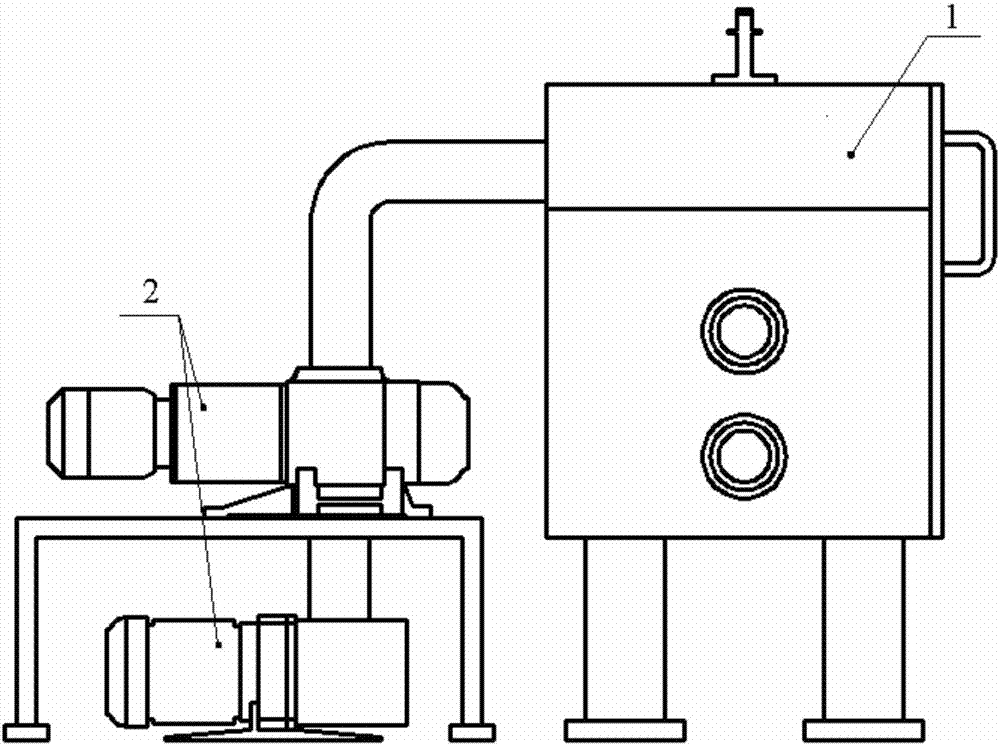
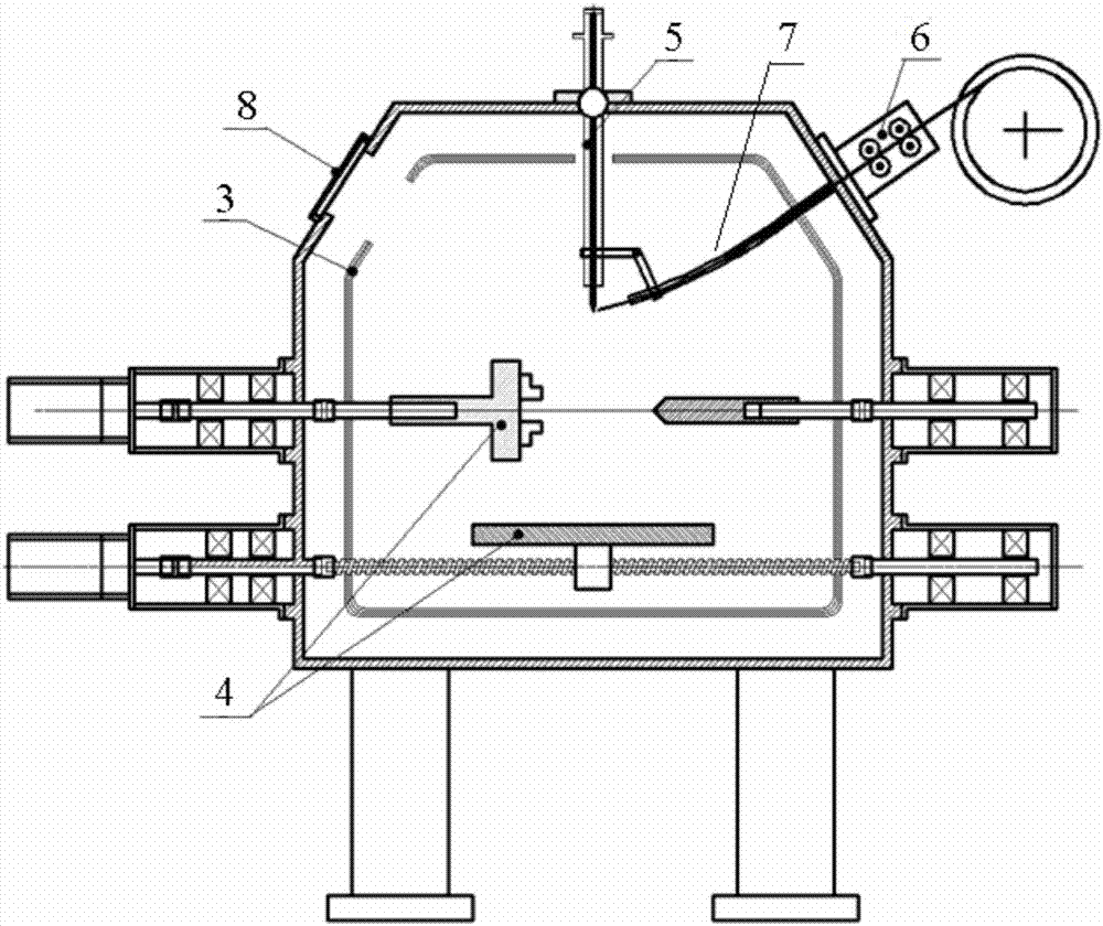
[0031] See attached figure 1 , 2 As shown, the welding device includes a furnace body 1 and a vacuum pump group 2 that provides vacuum / inert gas protection for the furnace body 1. A heating chamber 3 as a basic heat source is arranged in the furnace body 1, and a high temperature resistant CNC mobile workbench 4, heating chamber 3 surrounds the weldment to heat the weldment in an all-round way, and a welding torch 5 as a local heating welding heat source is arranged above the heating chamber 3, and the lower end of the welding torch 5 extends vertically into the heating chamber 3 The wire feeding mechanism 6 is installed between the shell of the furnace body 1 on one side of the welding torch 5 and the heating chamber 3, and the wire guide tube 7 of the wire feeding mechanism 6 is introduced into the heating chamber 3. The lower end of the welding torch 5 It is fixed together with the end of the wire guide tube 7 to ensure that the wire can be accurately fed into the molten p...

Embodiment 2

[0048] Welding device is identical with embodiment 1, adopts the method step of this welding device to carry out welding as follows:

[0049] step one

[0050] 2mm thick K465 cast superalloy plate, flat butt joint. The electric arc is used as the generation method of the welding heat source. Before welding, clamp the flat mouth of the K465 alloy plate in the tooling and place it on the mobile work platform. The surface of the test plate is 2.0mm away from the tungsten needle. Record the relative position of the tungsten needle and the welding seam in the numerical control system. vacuum. When the vacuum degree reaches below 2*10‐1Pa, stop vacuuming. Set the basic heating temperature to 700°C, turn on the heating power of the heating chamber, and fill the furnace body with argon or other inert gas at the same time to ensure that the internal pressure of the furnace body is less than 0.1MPa during the heating process; when the internal temperature of the furnace body reaches ...


PUM


Abstract

The invention discloses a combined heat source welding method and device in vacuum/ in a protective atmosphere. The combined heat source welding method in vacuum/ in the protective atmosphere comprises the steps that in vacuum/ in the protective atmosphere, a heating furnace used as a basic heat source conducts overall heating on a welded piece to heat the welded piece to the high temperature of 600-1200 DEG C, and the temperature is kept; then, a welding gun used as a local heating heat source is used for heating and melting the area to be welded, and a weld joint is formed after cooling and solidification; the welded piece is cooled to the indoor temperature at a set cooling speed under the action of the basic heat source, and then the welding process is completed. The combined heat source welding device in vacuum/ in the protective atmosphere is composed of a vacuum pump group, the furnace, a heating chamber, a welding power source, a basic heating power source, a control cabinet, a high-temperature-resistant numerical control moving mechanism, the welding gun and a wire feeding mechanism. By the adoption of the combined heat source welding method in vacuum/ in the protective atmosphere, welding cracks of low-plasticity metal materials at the indoor temperature can be effectively avoided.

Description

technical field [0001] The invention relates to a combined heat source welding method and device thereof under vacuum / protective atmosphere, belonging to the field of welding technology. Background technique [0002] With the development of the aerospace industry, the performance requirements for high-temperature structural materials are getting higher and higher, not only high temperature resistance and oxidation resistance but also high specific strength and specific stiffness are required. Intermetallic compounds such as TiAl are recognized as the most potential high-temperature structural materials for their low density, high modulus, and excellent high-temperature strength, creep resistance, oxidation resistance, and flame retardancy. [0003] This type of alloy itself and its connection technology with dissimilar materials are one of the key technologies for the engineering application of this type of material. At present, the connection of such materials at home and ...

Claims


Application Information

Patent Timeline
Patent Type & Authority Applications(China)
IPC IPC(8): B23K9/167B23K9/32
CPCB23K9/167B23K9/32
Inventor 程耀永熊华平张学军张国栋袁鸿郭绍庆
Owner AVIC BEIJING INST OF AERONAUTICAL MATERIALS
Why Eureka
Try Eureka