Power circulation system combined with hydrogen gas turbine and hydrogen fuel cells
A fuel cell and gas turbine technology, which is applied in the direction of fuel cells, gas turbine devices, machines/engines, etc., can solve the problems of low energy conversion efficiency, high cycle efficiency, high power density, and maximum power that cannot meet the demand, so as to achieve full utilization and improve The effect of work performance
- Summary
- Abstract
- Description
- Claims
- Application Information
AI Technical Summary
Problems solved by technology
Method used
Image

Examples
Embodiment 1
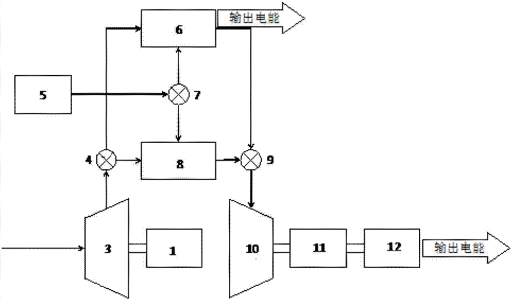
[0027] like figure 1 Shown is a combined power cycle system of a hydrogen gas turbine and a hydrogen fuel cell provided in this embodiment.
[0028] The hydrogen outlet of the hydrogen storage system 5 is connected to the inlet of the B valve 7 , the first outlet of the B valve 7 is connected to the hydrogen inlet of the hydrogen fuel cell 6 , and the second outlet of the B valve 7 is connected to the hydrogen inlet of the combustion chamber 8 . The hydrogen storage system 5 provides hydrogen for the hydrogen fuel cell 6 and the combustion chamber 8 , and controls and distributes the hydrogen flow to the combustion chamber 8 and the hydrogen fuel cell 5 through the B valve 7 .
[0029] The compressor 3 can be a low-pressure compressor, a medium-pressure compressor or a high-pressure compressor. The inlet of the compressor 3 is connected to the atmosphere, the outlet of the compressor 3 is connected to the inlet of the A valve 4, the first outlet of the A valve 4 is connected ...
Embodiment 2
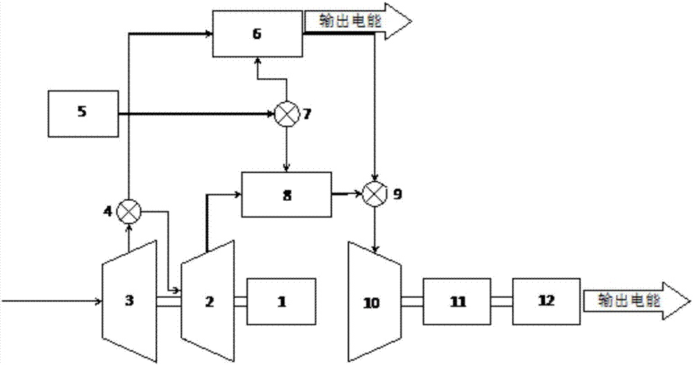
[0033] like figure 2 Shown is a combined power cycle system of a hydrogen gas turbine and a hydrogen fuel cell provided in this embodiment.
[0034] The difference from the system described in Embodiment 1 is that a high-pressure compressor 2 is added on the connecting branch between the compressor 3 and the combustor 8 of the hydrogen gas turbine. The second outlet of the A valve 4 is connected to the inlet of the high-pressure compressor 2, the outlet of the high-pressure compressor 2 is connected to the air inlet of the combustion chamber 8, the compressor 3, the high-pressure compressor 2, and the motor 1 are connected in sequence, and the motor 1 Simultaneously drive compressor 3 and high-pressure compressor 2.
[0035] Likewise, the compressor 3 may be a low-pressure compressor, a medium-pressure compressor or a high-pressure compressor. In this embodiment, the compressor 3 is a low-pressure compressor.
[0036] The efficiency and power density of the hydrogen gas tur...
Embodiment 3
[0038] This embodiment is used to illustrate the working principle of the combined power cycle system of the hydrogen gas turbine and the hydrogen fuel cell described in the above embodiments 1-2.
[0039] The system can work in three operating modes: hydrogen fuel cell 6 alone operation mode, hydrogen gas turbine alone operation mode, hydrogen fuel cell 6 and hydrogen gas turbine combined operation mode.
[0040] The hydrogen fuel cell 6 is suitable for a stable working state, and when the system needs to output part of the power with high efficiency, the hydrogen fuel cell operates alone. At this time, the B valve 7 is activated to connect the hydrogen storage system 5 with the hydrogen fuel cell 6, and the hydrogen storage system 5 is disconnected from the combustion chamber 8; the A valve 4 is activated to connect the compressor 3 with the hydrogen fuel cell 6, and the compressor 3 is connected to the combustion chamber 8. The combustion chamber 8 is disconnected; the hydr...
PUM
 Abstract
Description
Claims
Application Information
 - Generate Ideas
- Intellectual Property
- Life Sciences
- Materials
- Tech Scout
- Unparalleled Data Quality
- Higher Quality Content
- 60% Fewer Hallucinations
Browse by: Latest US Patents, China's latest patents, Technical Efficacy Thesaurus, Application Domain, Technology Topic, Popular Technical Reports.
© 2025 PatSnap. All rights reserved.Legal|Privacy policy|Modern Slavery Act Transparency Statement|Sitemap|About US| Contact US: help@patsnap.com