Strip vacuum plasma film-plating system

A plasma and coating system technology, applied in the field of plasma coating system, can solve the problems of low coating speed, large force, uneven color, etc., to achieve uniform and single film layer, ensure vacuum degree, and ensure high quality Effect

Active Publication Date: 2017-07-04
广州市中昊装饰材料有限公司
View PDF3 Cites 3 Cited by
  • Summary
  • Abstract
  • Description
  • Claims
  • Application Information

AI Technical Summary

Problems solved by technology

[0005] The purpose of the present invention is to provide a solution to the existing periodic and continuous vacuum plasma coating equipment, which has a small amount of furnace for coating metal strips, cannot be used for fast and efficient deposition of uniform films, and equipment expansion Few functions, high investment in equipment, low utilization rate and high energy consumption, provide a vacuum plasma coating system mainly used for strips
[0006] In order to overcome the low production efficiency, high energy consumption, complex tooling and fixtures, low product utilization rate, low target material utilization rate, low reprocessing utilization rate, low coating speed, uneven color, and relatively large stress in the above-mentioned prior art , easy to deform, difficult to manufacture and relatively large cost of materials. The present invention adopts the following technical solutions:

Method used


Image

  • Strip vacuum plasma film-plating system
  • Strip vacuum plasma film-plating system
  • Strip vacuum plasma film-plating system

Examples


Embodiment 1

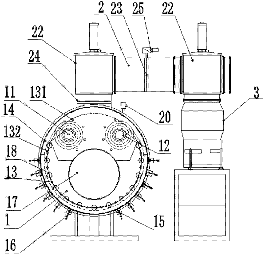
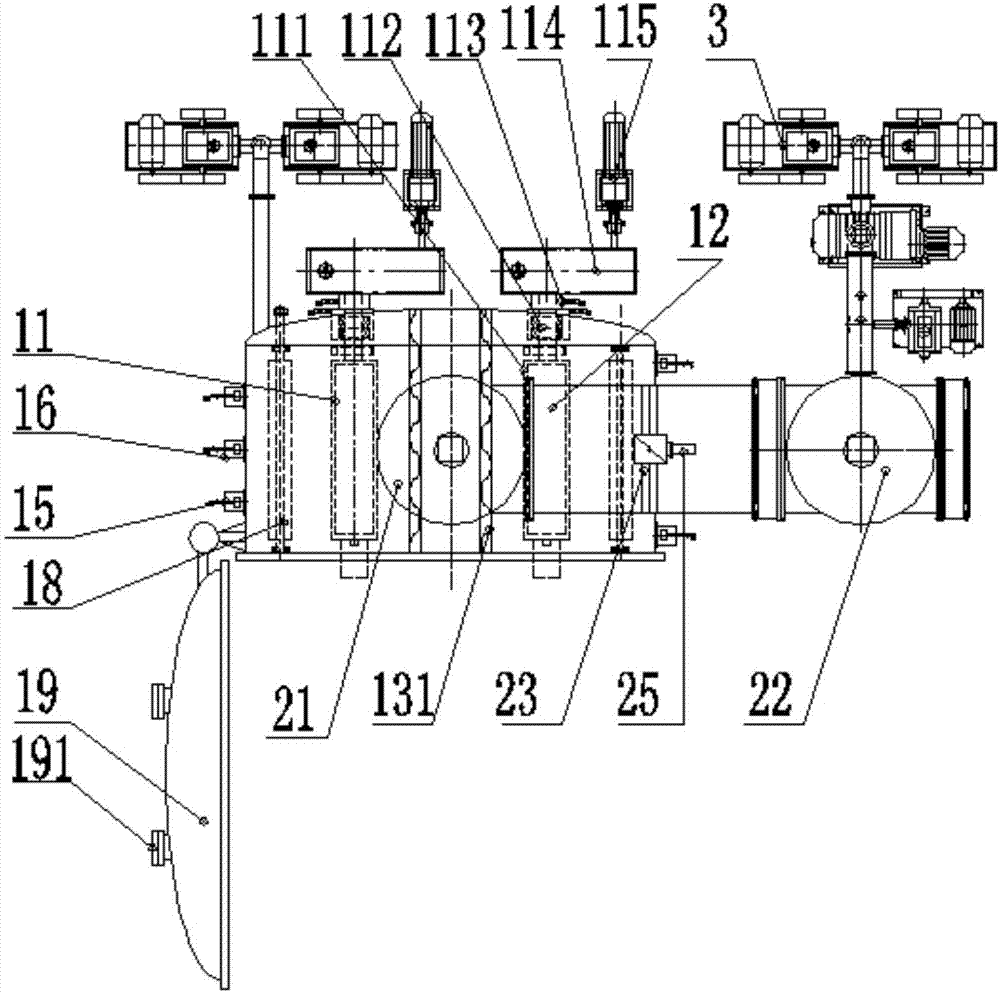
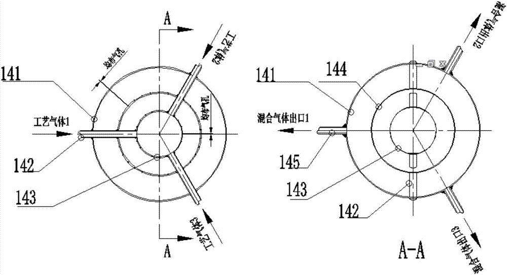
[0035] Such as Figure 1 to Figure 4 As shown, a strip vacuum plasma coating system includes a vacuum obtaining system 3, a vacuum connecting pipeline 2 and a continuous coating chamber 1 with a circular structure or an elliptical structure, and the vacuum obtaining system 3 connects the continuous vacuum through the vacuum connecting pipeline 2. The coating chamber 1 is connected, and the vacuum obtaining system 3 is a conventional vacuuming device; the continuous coating chamber 1 includes an unwinding device 11, a winding device 12, a heat pipe mechanism 13, an inlet and outlet gas mixing device 14 and a cathode target 15. The filtered cathode target generating device 16, the unwinding device 11, the winding device 12 and the heat pipe mechanism 13 are located inside the continuous coating chamber 1, and the inlet and outlet gas mixing device 14 and the filtered cathode target generating device 15 are located on the side of the continuous coating chamber 1 On the wall, the ...

Embodiment 2

[0047] Such as Figure 3 to Figure 5 As shown, as in the structure of Embodiment 1, a vacuum obtaining system 3 is connected to two continuous vacuum coating chambers 1 through a vacuum connecting pipe 2 . The parts on the vacuum connection pipe 2 that are diverted to the continuous vacuum coating chamber 1 are divided into A and B, and the continuous vacuum coating chamber 1 is divided into a vacuum coating chamber 1 and a vacuum coating chamber 2.

[0048] After the coating in vacuum coating chamber 1 is completed, close the vacuum chamber furnace door of vacuum coating chamber 2, close the first valve, and open the second valve B to allow the gas in vacuum coating chamber 2 to flow into vacuum coating chamber 1. When the vacuum degree reaches equilibrium Finally, after closing the second valve A, open the first valve, vacuumize the vacuum coating chamber two, open the vacuum chamber furnace door 19 of the vacuum coating chamber one simultaneously, load and unload the strip,...


PUM


Abstract

The invention discloses a strip vacuum plasma film-plating system. A vacuum obtaining system is connected to multiple continuous type film-plating chambers through a vacuum connection pipeline. Each continuous type film-plating chamber comprises an unreeling device, a reeling device, and a heating tube mechanism, which are arranged in the continuous type film-plating chamber, and also comprises an inlet air and outlet air mixing device and a filter cathode target generation device, which are arranged on the lateral wall of the continuous type film-plating chamber. A first valve and a second valve are arranged on the vacuum connection pipeline. The first valve is arranged in the outlet of the vacuum obtaining system. The second valve is arranged above the joint between the vacuum connection pipe and the continuous type film-plating chambers. The design of the provided strip vacuum plasma film-plating system is scientific and reasonable. The operation is stable, the deviation is avoided, the automation degree is improved, at the same time, the product quality is largely improved, the production efficiency is improved, and more economic benefits are generated.

Description

technical field [0001] The invention relates to the coating field, in particular to a strip vacuum plasma coating system. Background technique [0002] The existing technology of vacuum plasma coating equipment for coating continuous strip or plate metal products has disadvantages such as backward technology, high energy consumption, uneven film thickness, and low output. The equipment for processing such products generally includes periodic There are two types of vacuum plasma coating equipment and continuous vacuum plasma coating equipment: [0003] 1. It is a periodic vacuum plasma coating equipment, which originates from the fact that its production and processing products are produced in the form of a small amount of single-loading as a production cycle. The product placement is relatively small, the size is small, and the weight is light. Summarize the results This kind of equipment generally has the following disadvantages: 1. The production efficiency is low. Every ...

Claims


Application Information

Patent Timeline
IPC IPC(8): C23C14/56
Inventor 何培忠
Owner 广州市中昊装饰材料有限公司
Why Eureka
Try Eureka