
Negative pressure deodorization system

A negative pressure and cabinet technology, applied in the field of negative pressure deodorization system, can solve the problems of insufficient deodorization and sterilization, high energy consumption, and pollution of the surrounding environment, and achieve good adaptability and stability, and improve deodorization Odor effect, effect of promoting deodorization effect

Pending Publication Date: 2017-07-07
HUNAN PUTAIER ENVIRONMENTAL CO LTD
View PDF9 Cites 1 Cited by
  • Summary
  • Abstract
  • Description
  • Claims
  • Application Information

AI Technical Summary

Problems solved by technology

The former mainly uses incense, camphor balls or other aromatic substances to cover the odor in the toilet. This method is inefficient and cannot fundamentally remove the odor and kill germs, and inhaling the mixed gas of the masking agent and the odor may cause Cause dizziness, vomiting and other symptoms, causing different degrees of harm to the human body
The latter is to install exhaust devices in public toilets to directly discharge the odor into the atmosphere, which not only consumes high energy, fails to achieve the effect of deodorization and sterilization, but also pollutes the surrounding environment

Method used


Image

  • Negative pressure deodorization system
  • Negative pressure deodorization system
  • Negative pressure deodorization system

Examples


Embodiment Construction

[0031] In order to enable those skilled in the art to better understand the technical solution of the present invention, the present invention will be described in detail below in conjunction with the accompanying drawings. The description in this part is only exemplary and explanatory, and should not have any limiting effect on the protection scope of the present invention. .

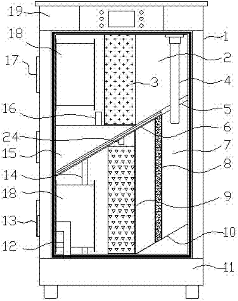
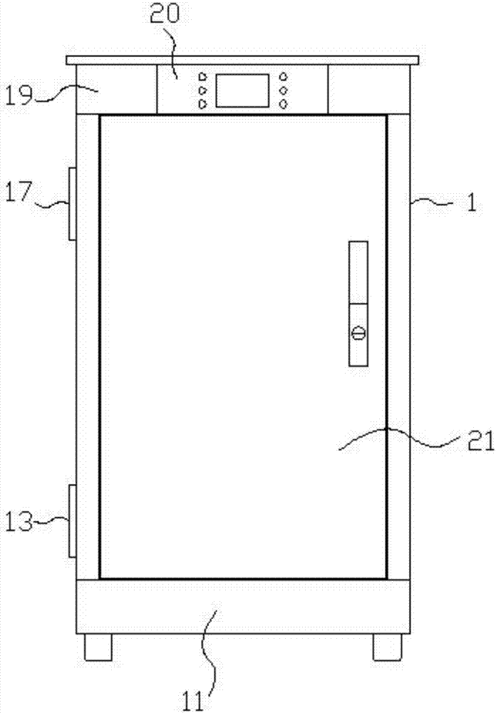
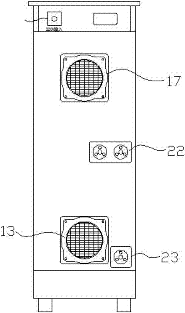
[0032] Such as Figure 1-Figure 9As shown, the specific structure of the present invention is: a negative pressure deodorization system, which includes a cabinet 1, the inner cavity of the cabinet 1 is divided into an upper chamber 2 and a lower chamber 7 by a partition 6; There is an air guide port 5 for connecting the upper chamber 2 and the lower chamber 7; the side of the cabinet body 1 is provided with an air outlet 17 connected to the upper chamber 2; the side of the cabinet body 1 is provided with an air inlet 13 connected to the lower chamber 7 ; In the lower chamber 7, a blower fan 18, a micr...


PUM

PropertyMeasurementUnit
particle diameteraaaaaaaaaa

Abstract

The invention discloses a negative pressure deodorization system. The negative pressure deodorization system comprises a cabinet, and an inner cavity of the cabinet is partitioned into an upper cavity and a lower cavity through a partition plate. The partition plate is provided with an air guide port for making the upper cavity and the lower cavity communicated. The side edge of the cabinet is provided with an air outlet communicated with the upper cavity and is further provided with an air inlet communicated with the lower cavity. In the lower cavity, a fan, a microorganism attachment box and a dehydration layer are arranged from the air inlet to the interior in sequence. In the upper cavity, a fan, an activated carbon filtration layer and a high-energy ion tube are arranged from the air outlet to the interior in sequence. The air guide port is located between the high-energy ion tube and the dehydration layer. A bottom box is arranged at the bottom of the cabinet. A circulation box is arranged on the partition plate. The upper end of the microorganism attachment box is communicated with the circulation box, and the bottom end of the microorganism attachment box is communicated with the bottom box. A water pump is arranged in the circulation box and connected with sprayers through pulse electronic valves. The sprayers are evenly arranged at the upper end of the microorganism attachment box. The water pump is communicated with the bottom box through a liquid suction tube. A microbial deodorizer is placed in the bottom box. The negative pressure deodorization system is good in deodorization and sterilization effect, capable of preventing secondary pollution and convenient to install and use.

Description

technical field [0001] The invention belongs to the technical field of deodorization, in particular to a negative pressure deodorization system. Background technique [0002] With the development of society, public toilets have become an important symbol of modern urban civilization, and they have been basically popularized in large and medium-sized cities, especially in places with large population movements, such as stations, vegetable markets, tourist attractions, etc. Due to the large flow of people and frequent use, if it is not handled properly or not in time, it is easy to cause odor to spread, which will cause bacteria to breed, pollute the surrounding environment, and even cause the spread of germs. Therefore, it is very important to deodorize public toilets. At present, the traditional deodorization methods for public toilets mainly include odor masking and exhausting. The former mainly uses incense, camphor balls or other aromatic substances to cover the odor in...

Claims


Application Information

Patent Timeline
Patent Type & Authority Applications(China)
IPC IPC(8): B01D53/84B01D53/75B01D53/04B01D53/26A61L9/00
CPCA61L9/00B01D53/04B01D53/263B01D53/75B01D53/84B01D2259/80B01D2258/00B01D2257/304B01D2257/406Y02A50/20
Inventor 胡峻吴小国马威李海龙陈林李安华
Owner HUNAN PUTAIER ENVIRONMENTAL CO LTD
Learn More