Slot waveguide theory-based electromagnetic radiation suppression structure and application thereof

A technology of electromagnetic radiation and slot waveguide, which is applied in the direction of circuits, electrical components, electric solid devices, etc., can solve problems affecting the working performance of integrated circuits, heat dissipation, high price, and deterioration of high-frequency electromagnetic radiation, etc., to achieve miniaturization, electromagnetic Radiation suppression, reducing the effect of electromagnetic radiation

Active Publication Date: 2017-07-07
ZHEJIANG UNIV
View PDF5 Cites 8 Cited by
  • Summary
  • Abstract
  • Description
  • Claims
  • Application Information

AI Technical Summary

Problems solved by technology

However, grounding can effectively suppress electromagnetic radiation only at low frequencies, and has no obvious inhibitory effect on high-frequency electromagnetic radiation, and sometimes even deteriorates high-frequency electromagnetic radiation.
Although coating the absorbing material on the package cover and heat sink can effectively suppress electromagnetic radiation in different frequency bands, the absorbing material is expensive and will affect the working performance and heat dissipation of the integrated circuit.

Method used


Image

  • Slot waveguide theory-based electromagnetic radiation suppression structure and application thereof
  • Slot waveguide theory-based electromagnetic radiation suppression structure and application thereof
  • Slot waveguide theory-based electromagnetic radiation suppression structure and application thereof

Examples


Embodiment 1

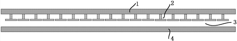
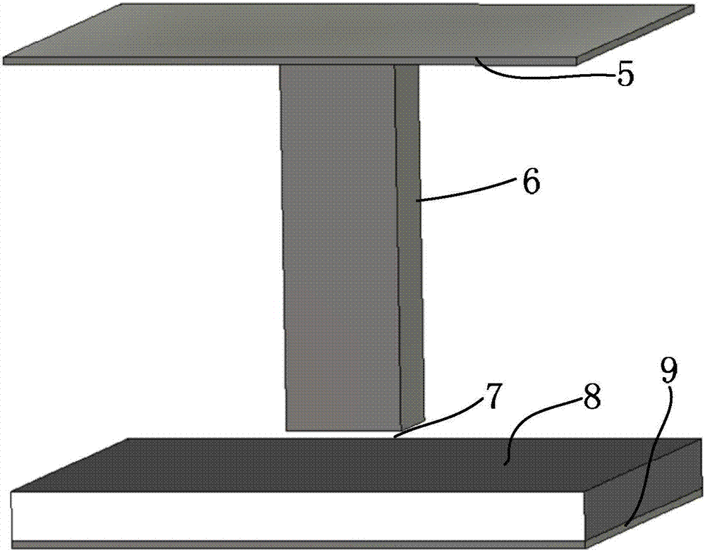
[0040] Such as Figure 4 As shown, a periodic electromagnetic bandgap EBG structure 2 is provided on the lower surface of the heat dissipation package cover 1 between the package substrate 4 and the heat dissipation package cover 1, and the periodic electromagnetic bandgap structure 2 is a pin-shaped structure uniformly distributed in a spaced array. Dimensional metal EBG structure, including a metal pin 6, the upper end of the metal pin 6 is fixed on the lower surface of the top metal plate 5 of the heat dissipation package cover or radiator, the package substrate 4 includes a dielectric layer 8 and a bottom metal plate 9, and the bottom metal plate of the package substrate 4 The board 9 serves as a metal ground plane, and there is an air gap 7 between the lower end of the metal pin 6 and the dielectric layer 8 of the packaging substrate 4 . Specific implementation According to the design requirements, adjust the period of the unit structure, the length and width of the metal...

Embodiment 2

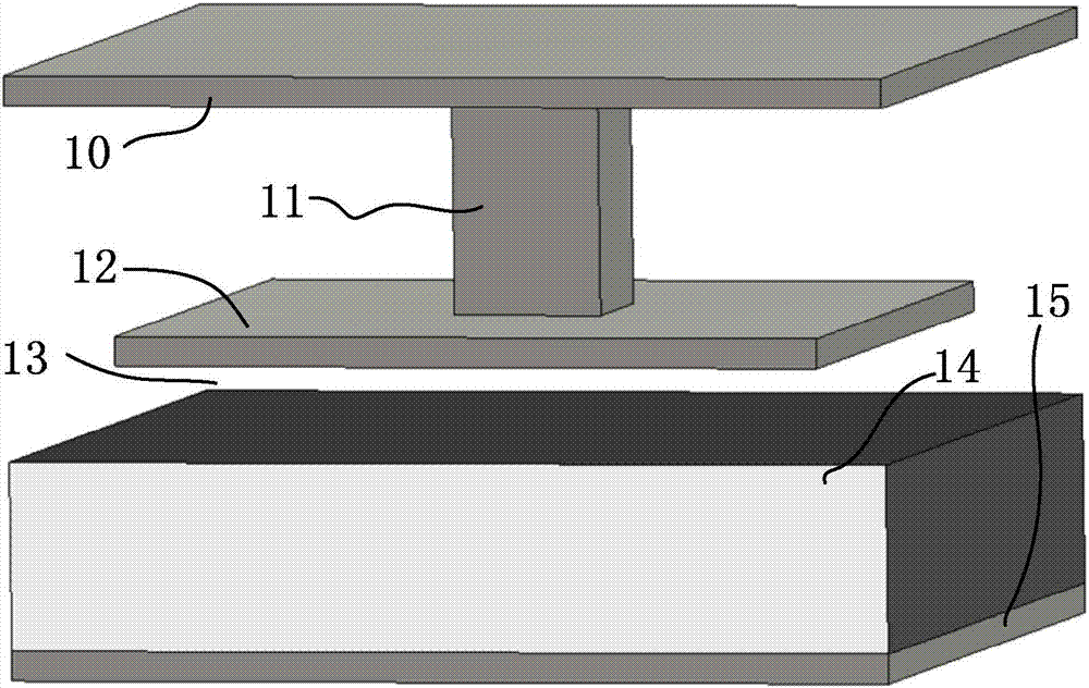
[0042] Such as Figure 5As shown, a periodic electromagnetic bandgap EBG structure 2 is provided on the lower surface of the heat dissipation package cover 1 between the package substrate 4 and the heat dissipation package cover 1, and the periodic electromagnetic bandgap structure 2 is a mushroom-shaped two-dimensional array uniformly distributed at intervals. Dimensional metal EBG structure, including metal pin 11 and metal patch 12, the upper end of metal pin 11 is fixed on the lower surface of the top metal plate 10 of the heat dissipation package cover or radiator, the lower end of metal pin 11 is connected to the center of the upper end of metal patch 12, and the metal The patch 12 is square, and there is an air gap 13 between the lower end of the metal patch 12 and the dielectric layer 14 of the package substrate 4. The package substrate 4 includes a dielectric layer 14 and a bottom metal plate 15, and the bottom metal plate 9 of the package substrate 4 serves as a metal...

Embodiment 3

[0046] Such as Figure 6 As shown, the lower surface of the heat sink 1 between the package substrate 4 and the heat sink 1 is provided with a periodic electromagnetic bandgap EBG structure 2, and the periodic electromagnetic bandgap structure 2 is a mushroom-shaped two-dimensional metal with an evenly spaced array. EBG structure.

[0047] Such as Figure 6 As shown, 19 is an inter-board heat sink commonly used in chip packaging. Its upper part is a heat dissipation tooth for heat dissipation, and its lower surface is a smooth metal surface. Thin colloidal connections. Considering the actual application scenario, a smooth metal surface is reserved in the middle part of the lower surface of the heat sink to provide enough space for the package cover and the package substrate, so the mushroom-shaped two-dimensional metal EBG structure is arranged in the ring area around the package cover, and the periodic structure The arrangement and quantity can be adjusted accordingly acco...


PUM


Abstract

The invention discloses a slot waveguide theory-based electromagnetic radiation suppression structure and an application thereof. Periodic electromagnetic bang gap (EBG) structures are arranged between a packaging substrate and a heat dissipation packaging cover or between the packaging substrate and a radiator, so as to realize a boundary condition of PMC within the required frequency band to perform electromagnetic radiation suppression; specifically, the periodic electromagnetic bang gap structures refer to pin type two-dimensional metal EBG structures and mushroom type two-dimensional metal EBG structures which are in array and uniform distribution at intervals; and an air gap is formed between the electromagnetic bang gap structure and the packaging substrate, so that the distance between the bottom surface of the electromagnetic bang gap structure and the packaging substrate is less than 1 / 4 of corresponding wavelength of the center frequency of the working frequency bands. By adoption of the slot waveguide theory-based electromagnetic radiation suppression structure and the application thereof, the electromagnetic radiation in the working frequency bands can be effectively lowered, particularly, an obvious suppression effect is played on high-frequency electromagnetic radiation; miniaturization of design dimensions are realized; and the electromagnetic radiation suppression structure can be applied to packaging design of a chip, a printed circuit board and the like.

Description

technical field [0001] The invention relates to an electromagnetic radiation suppression structure based on the slot waveguide theory and its application, in particular to an electromagnetic radiation suppression structure based on the slot waveguide theory and its application. [0002] technical background [0003] With the rapid development of electronic and electrical equipment, the data transmission rate and clock frequency in high-speed digital systems have increased rapidly, and electromagnetic interference and heat dissipation have become a major challenge for the next generation of electronic products. In order to solve the heat dissipation problem, a package cover and a heat sink are usually added in the package design of the printed circuit board and the chip. Traditional heat sinks and package lids are usually made of metals with high thermal conductivity and high conductivity. With the continuous increase in the operating speed of integrated circuits, it is easy t...

Claims


Application Information

Patent Timeline
Patent Type & Authority Applications(China)
IPC IPC(8): H05K9/00H01L23/552
CPCH05K9/002H01L23/552
Inventor 李尔平杨晓莉成萍李永胜祝栋柯黄银涛李斌
Owner ZHEJIANG UNIV
Why Eureka
Try Eureka