Integrated biosensor and preparation method thereof

A biosensor, integrated technology, applied in the direction of phase impact characteristic measurement, etc., can solve the problems of unsuitable for low-cost system applications, expensive, limited measurement range, etc., to achieve easy array sensing, reduce loss and complexity , low-cost effect

Active Publication Date: 2017-07-11
CHINA ELECTRONIC TECH GRP CORP NO 38 RES INST
View PDF5 Cites 6 Cited by
  • Summary
  • Abstract
  • Description
  • Claims
  • Application Information

AI Technical Summary

Problems solved by technology

For a microring resonator, when the concentration of the target substance to be measured changes, the effective refractive index of the microring waveguide changes, resulting in a certain change in the resonance peak of the microring. A single microring based on biosensing, using a common Microring structure and slot waveguide structure, the detection limit is from 10-4 to 10-7. In general, the two basic detection methods for optical sensing are wavelength scanning and intensity scanning. However, for the wavelength scanning method, for The normal way to measure the shift of the resonance peak is to combine photodetectors and high-precision tunable lasers, or to use broadband light sources and spectrometer (OSA) analysis systems. However, these devices are usually relatively expensive and not suitable for low-cost systems. application, and for OSA or tunable lasers, the detection sensitivity is limited by the detection accuracy of OSA and tunable lasers; and for intensity scanning, set a wavelength, when the resonance peak drifts, the output light intensity will change, However, due to the small width of the resonance peak, the response power quickly approaches zero as the refractive index changes, so the measurement range is limited

Method used


Image

  • Integrated biosensor and preparation method thereof
  • Integrated biosensor and preparation method thereof
  • Integrated biosensor and preparation method thereof

Examples


Embodiment Construction

[0025] The embodiments of the present invention are described in detail below. This embodiment is implemented on the premise of the technical solution of the present invention, and detailed implementation methods and specific operating procedures are provided, but the protection scope of the present invention is not limited to the following implementation example.

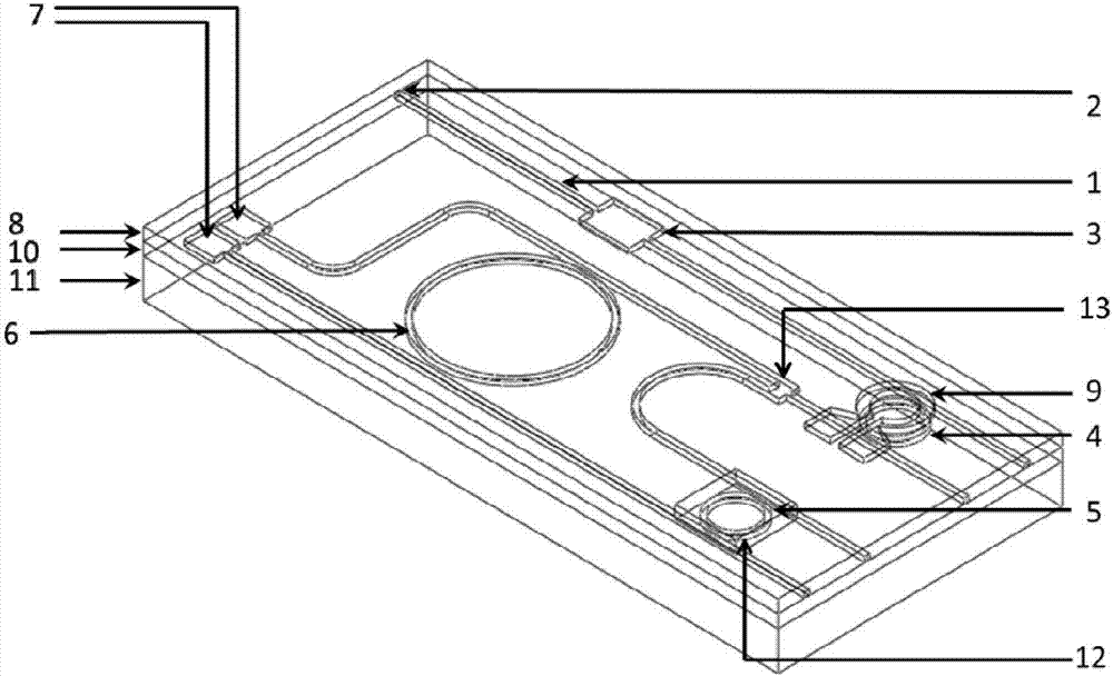
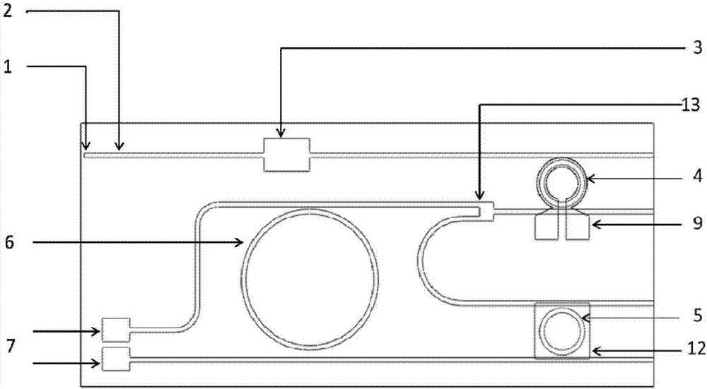
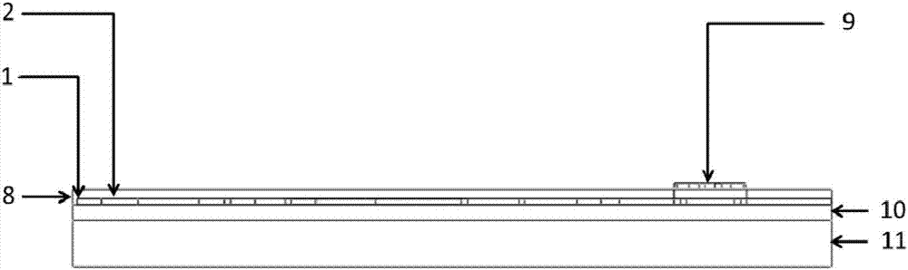
[0026] like Figure 1~3 As shown, this embodiment includes a body 1, a silicon dioxide buried layer 10, a silicon substrate layer 11 and a silicon dioxide upper cladding layer 8, the silicon dioxide buried layer 10 is arranged under the body 1, and the silicon dioxide The upper cladding layer 8 covers the body 1, the body 1 is sandwiched between the silicon dioxide buried layer 10 and the silicon dioxide upper cladding layer 8, and the silicon substrate layer 11 is arranged on the silicon dioxide buried layer Bottom of 10.

[0027] The thickness h3 of the body 1 is 220 nm, the thickness h2 of the silicon dioxide ...


PUM

PropertyMeasurementUnit
widthaaaaaaaaaa
thicknessaaaaaaaaaa
thicknessaaaaaaaaaa

Abstract

The invention discloses an integrated biosensor and a preparation method thereof, wherein an incident waveguide is arranged on the input end of a body, the input end of a waver filter is positioned on the input end of the body, the output end of the wave filter is positioned on the output end of the body, a thermal tuning micro ring is arranged on the output end of the wave filter, the input end of a power splitter is positioned on the download end of the thermal tuning micro ring, a sensing micro ring is arranged on the other output end of the power splitter, a germanium-silicon detector is arranged on the output port of the download end of the sensing micro ring, a heating electrode is arranged on the thermal tuning micro ring, and the sensing micro ring is positioned in a sensing window. According to the present invention, the photodetector and the sensing passive device are monolithically integrated so as to easily perform the array sensing; the input light source is the broad spectrum light source, and the external optical power meter is not required, such that the loss and the complexity of the system are reduced; and the expensive tunable laser and the high-precision spectrometer are not required so as to substantially reduce the whole system cost.

Description

technical field [0001] The invention relates to a microelectronic biosensor, in particular to an integrated biosensor and a preparation method thereof. Background technique [0002] As a traditional microelectronic material, silicon material has been widely used in the CMOS field, and silicon material has a very low loss coefficient in the communication band, and is a good waveguide material. In recent years, silicon photonics has gradually become a hot topic. In the field of research, great breakthroughs have been made in photoelectric modulators, splitters and various active and passive devices. At the same time, researchers are gradually applying silicon photonics to various sensing fields, including biological, environmental, chemical detection, Due to the compatibility of silicon with CMOS and high refractive index, researchers have developed integrated optical sensors based on various structures, including Mach-Zehnder interferometers, surface plasmons, and microcaviti...

Claims


Application Information

Patent Timeline
Patent Type & Authority Applications(China)
IPC IPC(8): G01N21/41
CPCG01N21/41
Inventor 金里周杰方俏然赵恒吴浩然冯俊波郭进崔乃迪
Owner CHINA ELECTRONIC TECH GRP CORP NO 38 RES INST
Why Eureka
Try Eureka