Regenerative cooling double flow channel scheme strengthening heat exchange through spray wall impingement

A technology for regenerative cooling and enhanced heat exchange, which is applied in combustion methods, lighting and heating equipment, combustion chambers, etc., and can solve problems such as large thermal load gradient on the combustion chamber wall, unstable fuel nozzle flow supply, and difficult fuel supply system design. , to solve the problem of instability and fuel fluctuation, enhance the overall atomization effect, and prevent the deterioration of heat transfer

Active Publication Date: 2017-07-14
PLA PEOPLES LIBERATION ARMY OF CHINA STRATEGIC SUPPORT FORCE AEROSPACE ENG UNIV
View PDF8 Cites 10 Cited by
  • Summary
  • Abstract
  • Description
  • Claims
  • Application Information

AI Technical Summary

Problems solved by technology

Using the traditional channel or pin-type cooling channel scheme will face the following problems: First, the traditional cooling method based on forced convection heat transfer, because the heat absorption capacity of the coolant varies along the course, the heat transfer process is uneven, and the heat on the wall of the combustion chamber The load gradient is large, and some local areas with high heat flux density often suffer from poor heat transfer due to insufficient cooling; secondly, due to the high heat flux density, in order to increase the convective heat transfer area, the flow area of ​​the channel is usually small, high temperature Coking of kerosene is easy to block the flow channel
Thirdly, the unstable gas-liquid two-phase fuel formed in the heat exchange process is likely to cause instability in the flow supply of the fuel nozzle, which brings difficulties to the design of the fuel supply system

Method used


Image

  • Regenerative cooling double flow channel scheme strengthening heat exchange through spray wall impingement
  • Regenerative cooling double flow channel scheme strengthening heat exchange through spray wall impingement
  • Regenerative cooling double flow channel scheme strengthening heat exchange through spray wall impingement

Examples


Embodiment Construction

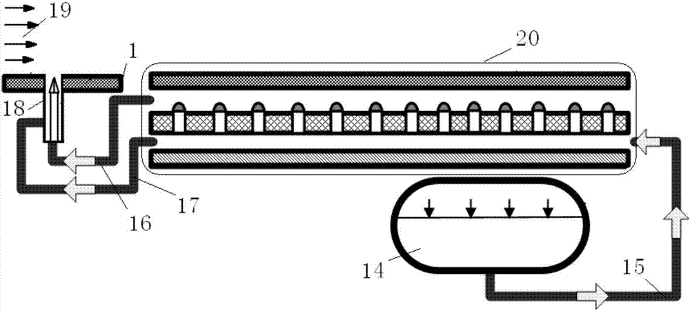
[0022] Such as figure 1 Schematic diagram of the self-generating cooling process of the endothermic hydrocarbon fuel of the scramjet engine shown. After the fuel stored in the storage tank 14 is extruded, it enters the nozzle 18 of the engine combustion system in gaseous and liquid forms respectively through the fuel supply pipeline to absorb heat on the double-layer heat exchange channel in the wall of the combustion chamber, and realizes Atomized, blended and combusted with supersonic air flow. The overall structure of the combustion chamber of the combined spray / convection cooling structure can choose a circular wall or a flat wall according to the overall configuration of the engine combustion chamber. Only the local structure of the combustion chamber is shown in the figure.

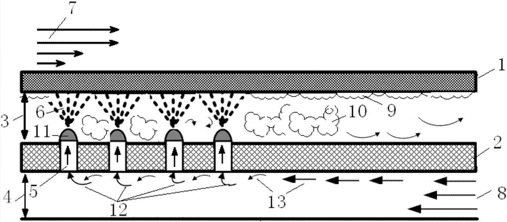
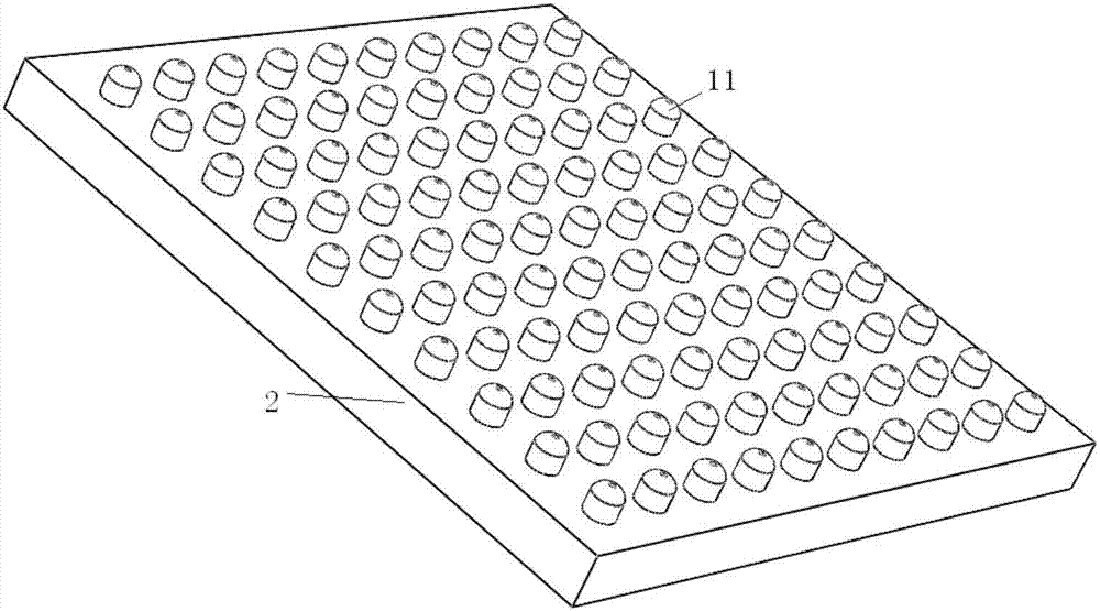
[0023] Such as figure 2 As shown, the combustion chamber wall structure of the spray / convection composite cooling structure is composed of an outer wall 1 and an inner wall 2, which are separate...


PUM


Abstract

The invention provides a heat exchange strengthening structure used for regenerative cooling of a supersonic combustion chamber through a spraying / convection composite type heat exchange mode. A double flow channel design is adopted, and the characteristic of the large heat flux of a spraying cooling mode is fully utilized to conduct heat exchange strengthening on the wall face of the combustion chamber. A scheme is composed of a double layer heat exchange scheme of the outer layer wall and the inner layer wall. A flow channel formed by partitioning of the outer layer wall and the inner layer wall is used for spray wall impingement strengthening heat exchange. Spraying nozzles are arranged on the inner layer wall. The number and distribution density of the spraying nozzles are determined according to the heat exchange strength and the heat exchange area. Part of heated liquid fuel and gaseous fuel formed by spray heat absorption are supplied to a nozzle of an engine combustion system in different phase states, and the liquid fuel is atomized in a mode of pneumatic atomization assisting. By adopting the design that a gas heat exchange flow channel and a liquid heat exchange flow channel are partitioned, the problem of flow supplying fluctuation caused by nonuniform gas and liquid distribution in the conveying process of the two phase flows of fuel after heat absorption to the combustion system is avoided.

Description

technical field [0001] The invention relates to a regenerative cooling dual-channel solution for strengthening heat exchange by spraying against a wall, which is used for thermal protection of the combustion chamber wall of a liquid heat-absorbing hydrocarbon fuel scramjet engine. Background technique [0002] The development of hypersonic vehicles is a hot spot in the development of the aerospace field today, and has attracted great attention from Europe, America, Russia and other countries. Because the high speed of the airflow in hypersonic flight will bring significant aerodynamic and thermal loads to the aircraft structure (especially the combustion chamber), the temperature of the uncooled combustion chamber can reach 3000K, completely exceeding the bearing capacity of known structural materials, so the design The key to a hypersonic vehicle is to solve the cooling problem of the vehicle. Unlike traditional jet engines, which use air to cool the walls of the combustio...

Claims


Application Information

Patent Timeline
Patent Type & Authority Applications(China)
IPC IPC(8): F23R3/36
Inventor 洪延姬席文雄徐庆尧钟文丽
Owner PLA PEOPLES LIBERATION ARMY OF CHINA STRATEGIC SUPPORT FORCE AEROSPACE ENG UNIV
Why Eureka
Try Eureka