
Flue gas recirculation method and flue gas recirculation system capable of reducing NOx emission of circulating fluidized bed boiler

A technology of circulating fluidized bed and recirculation system, which is applied in the directions of fluidized bed combustion equipment, combustion method, and fuel burned in a melted state, etc. Flue gas condensation corrosion and other problems, to achieve the effect of reducing the concentration of smoke and dust, avoiding sticking ash, and prolonging the operation period

Pending Publication Date: 2017-07-21
HUANENG CLEAN ENERGY RES INST
View PDF9 Cites 6 Cited by
  • Summary
  • Abstract
  • Description
  • Claims
  • Application Information

AI Technical Summary

Problems solved by technology

Due to the high temperature of the recirculating flue gas, especially the high concentration of smoke and dust, the recirculation fan can only be used for a short period of time; The fan is sent to the inlet of the existing primary fan. There are many problems in this method, such as dust sticking to the blade of the primary fan, excessive vibration, corrosion of flue gas condensation, etc., which seriously affect the continuous and stable operation of the flue gas recirculation system.

Method used


Image

  • Flue gas recirculation method and flue gas recirculation system capable of reducing NOx emission of circulating fluidized bed boiler

Examples


Embodiment Construction

[0029] The implementation of the present invention will be described in detail below in conjunction with the drawings and examples.

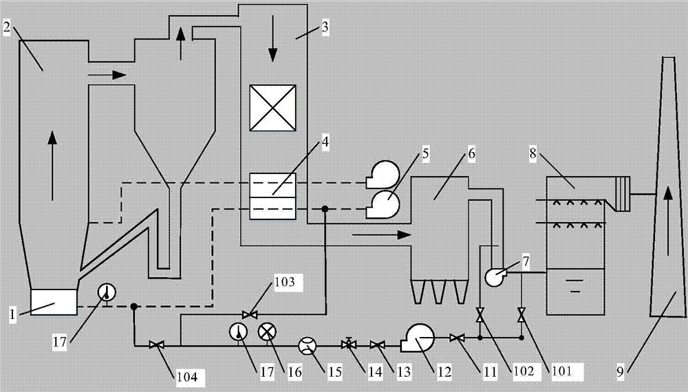
[0030] like figure 1 As shown, a flue gas recirculation system for reducing NOx emissions from circulating fluidized bed boilers according to the present invention includes recirculation pipes, valves, recirculation fan 12 and measuring devices for flue gas flow, pressure and temperature. In this system, after the flue gas leaves the furnace 2, it is discharged to the flue gas wet desulfurization device 8 through the tail flue 3 and the dust collector 6, and then discharged through the chimney 9. The air preheater 4 is installed in the tail flue 3 to reduce the temperature of the passing flue gas to obtain low-temperature flue gas. The low-temperature flue gas is dedusted by the dust collector 6 to greatly reduce the concentration of flue gas. The low-temperature flue gas is drawn out before entering the flue gas wet desulfurization device 8 wi...


PUM


Abstract

The invention discloses a flue gas recirculation method capable of reducing the NOx emission of a circulating fluidized bed boiler. Low-temperature flue gas after dust removal treatment and before wet desulphurization is pressurized, mixed with primary air and conveyed to an air chamber in the bottom of a hearth, and the amount of the primary air for fluidization is reduced and the proportion of secondary air is increased in the case of ensuring the invariable total amount of fluidizing air, so that the staged combustion characteristic of the secondary air is enhanced, and the NOx generated by combustion in the boiler is reduced. The invention further provides a flue gas recirculation system capable of reducing the NOx emission of a circulating fluidized bed boiler. The flue gas recirculation system comprises a recirculation pipeline, a recirculation fan, a valve, a flue gas flow meter, a flue gas pressure measurement component, a flue gas temperature measurement component and the like. The system is capable of remarkably lowering the running bed temperature of the circulating fluidized bed boiler, and better realizing air staging needed for low-nitrogen combustion, thereby greatly reducing the NOx emission of the circulating fluidized bed boiler. In addition, the system is capable of being used in combination with an SNCR or SCR technology, and further reducing the NOx emission of the circulating fluidized bed boiler.

Description

technical field [0001] The invention belongs to the technical field of boiler environmental protection, relates to the emission control of nitrogen oxides (NOx) in flue gas, and particularly relates to a flue gas recirculation method and system for reducing the NOx emission of a circulating fluidized bed boiler. Background technique [0002] Circulating fluidized bed boiler has the characteristics of wide fuel adaptability, high combustion efficiency and low investment cost, and has been developed rapidly at home and abroad. The technologies for reducing NOx emissions from coal-fired boilers are mainly divided into three categories: low NOx combustion in the furnace, selective non-catalytic reduction flue gas denitrification (SNCR) by injecting reducing agents in the furnace, and selective catalytic reduction flue gas denitrification by injecting reducing agents in the flue behind the furnace. Gas denitrification (SCR for short), these three types of technologies can be used...

Claims


Application Information

Patent Timeline
Patent Type & Authority Applications(China)
IPC IPC(8): F23C10/10F23C10/28F23C10/20F23J15/02
CPCF23C10/10F23C10/20F23C10/28F23J15/022
Inventor 郭涛张庆江建忠肖平
Owner HUANENG CLEAN ENERGY RES INST
Learn More