LED metal electrode structure and preparation method thereof

A metal electrode and electrode pattern technology, applied in circuits, electrical components, semiconductor devices, etc., can solve the problems of poor adhesion between electrodes and GaN, affecting the utilization rate of production evaporation machines, and difficult to control production yields, and achieve electrode stability. Good performance, automation of preparation process control, improvement of electrode stability and thermal stability

Active Publication Date: 2017-07-21
宁波安芯美半导体有限公司
View PDF9 Cites 3 Cited by
  • Summary
  • Abstract
  • Description
  • Claims
  • Application Information

AI Technical Summary

Problems solved by technology

There are two problems in the patent application number 200410058035.7: one is that the adhesion between the entire electrode and GaN will be poor, and the electrode will easily fall off during the subsequent wire bonding and bonding process; the other is that the voltage will increase
The electrode structure described in the patent application number 201410663429.9 also has two problems. First, Cr and Ni need to be vapor-deposited wit

Method used


Image

  • LED metal electrode structure and preparation method thereof
  • LED metal electrode structure and preparation method thereof
  • LED metal electrode structure and preparation method thereof

Examples


Example Embodiment

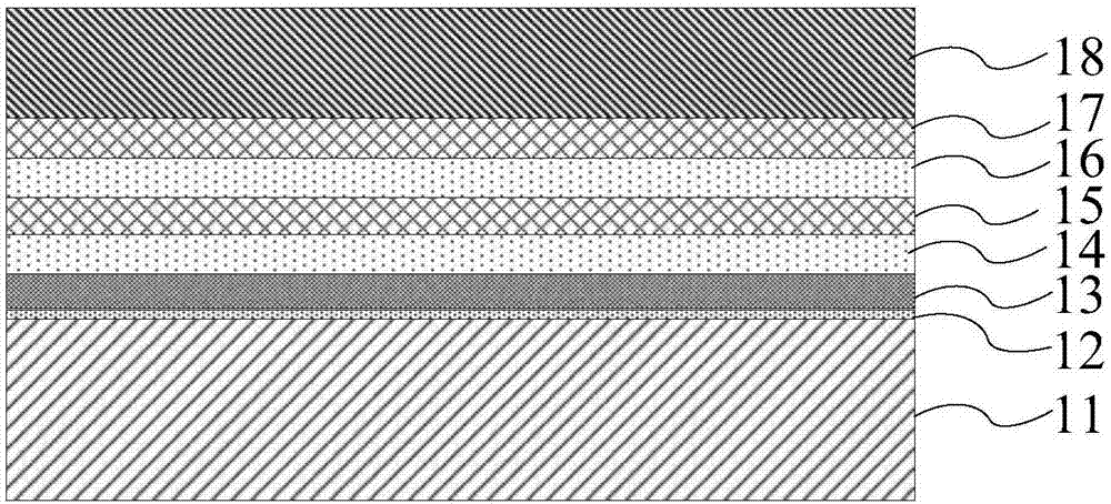
[0048] The following describes the implementation of the present invention through specific specific examples. Those skilled in the art can easily understand other advantages and effects of the present invention from the content disclosed in this specification. The present invention can also be implemented or applied through other different specific embodiments, and various details in this specification can also be modified or changed based on different viewpoints and applications without departing from the spirit of the present invention.

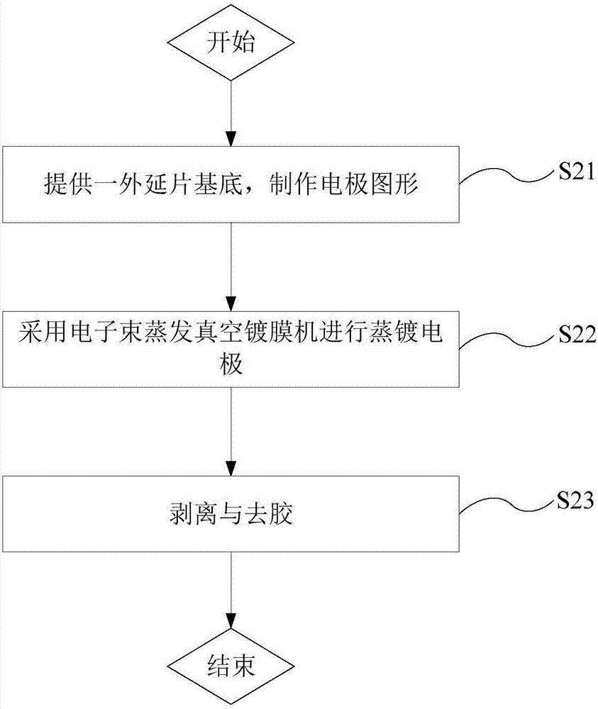
[0049] See Figure 1 to Figure 2 It should be noted that the illustrations provided in this embodiment only illustrate the basic idea of ​​the present invention in a schematic manner, so the figures only show the components related to the present invention instead of the number and shape of the components in actual implementation. And size drawing, the type, quantity, and ratio of each component can be changed at will during actual implementa...


PUM


Abstract

The invention provides an LED metal electrode structure and a preparation method thereof. The method comprises the steps of (S21) providing an epitaxial wafer and making an electrode pattern, (S22) carrying out evaporation of an electrode: orderly carrying out evaporation of a Cr layer, an Al layer, a first Ti layer, a first Ni layer, a second Ti layer, a second Ni layer, and an Au layer in a cavity of an electron beam evaporation vacuum film coating machine, and (S23) carrying out stripping and glue removing: stripping metal by using a blue film, and placing the electrode into a glue agent to carry out ultrasonic immersion after the stripping of the metal is completed. According to the LED metal electrode structure and the preparation method, the Al layer is closed to the Cr layer in the design, the Cr layer can play the role of adhesion and can reflect the light transmitted to P and N electrodes into a chip, the light reflected into the chip can be emitted outside again, thus the external quantum efficiency of an LED chip is improved, the function of Ti layer and Ni layer alternation mainly is the elimination of Ni stress, and a metal warpage abnormality in an evaporation process is prevented.

Description

technical field [0001] The invention relates to the field of semiconductor materials, in particular to an LED metal electrode structure and a preparation method thereof. Background technique [0002] Due to the advantages of high color purity, fast response, small size, and environmental protection, LED has undoubtedly become the most important light source technology. In recent years, with the continuous improvement of chip performance, the use of out-of-spec has become a normal state. On the premise that the performance of the chip itself meets the out-of-spec use, the requirements for the LED chip manufacturing process have also increased. [0003] At present, the electrode structure of LED chips generally adopts Cr / Al / Ti / Au. First of all, the first metal electrode structure, although the manufacturing process is simple, the light emitted by the light-emitting area inside the chip can be reflected to increase its light extraction efficiency, and its thermal stability is p...

Claims


Application Information

Patent Timeline
IPC IPC(8): H01L33/36H01L33/38H01L33/40H01L33/00
CPCH01L33/005H01L33/36H01L33/38H01L33/405
Inventor 吕振兴潘尧波张德刘亚柱
Owner 宁波安芯美半导体有限公司
Why Eureka
Try Eureka