Method for preparing thin-wall foam carbon-carbon nanotube composite material
A technology of carbon nanotubes and composite materials, which is applied in the field of preparation of thin-walled foam carbon-carbon nanotube composite materials, can solve the problems of weak bonding between carbon nanotubes and foam carbon, covering the structural characteristics of carbon nanotubes, and insufficient special properties To achieve the effect of rich structure and function, good shape and strong practicability
- Summary
- Abstract
- Description
- Claims
- Application Information
AI Technical Summary
Problems solved by technology
Method used
Image

Examples
Embodiment 1~21
[0042] Embodiment 1~21: refer to accompanying drawing.
[0043] A preparation method of thin-walled foamed carbon-carbon nanotube composite material, comprising the following steps:
[0044] a. Preparation of thin-walled foamed carbon:
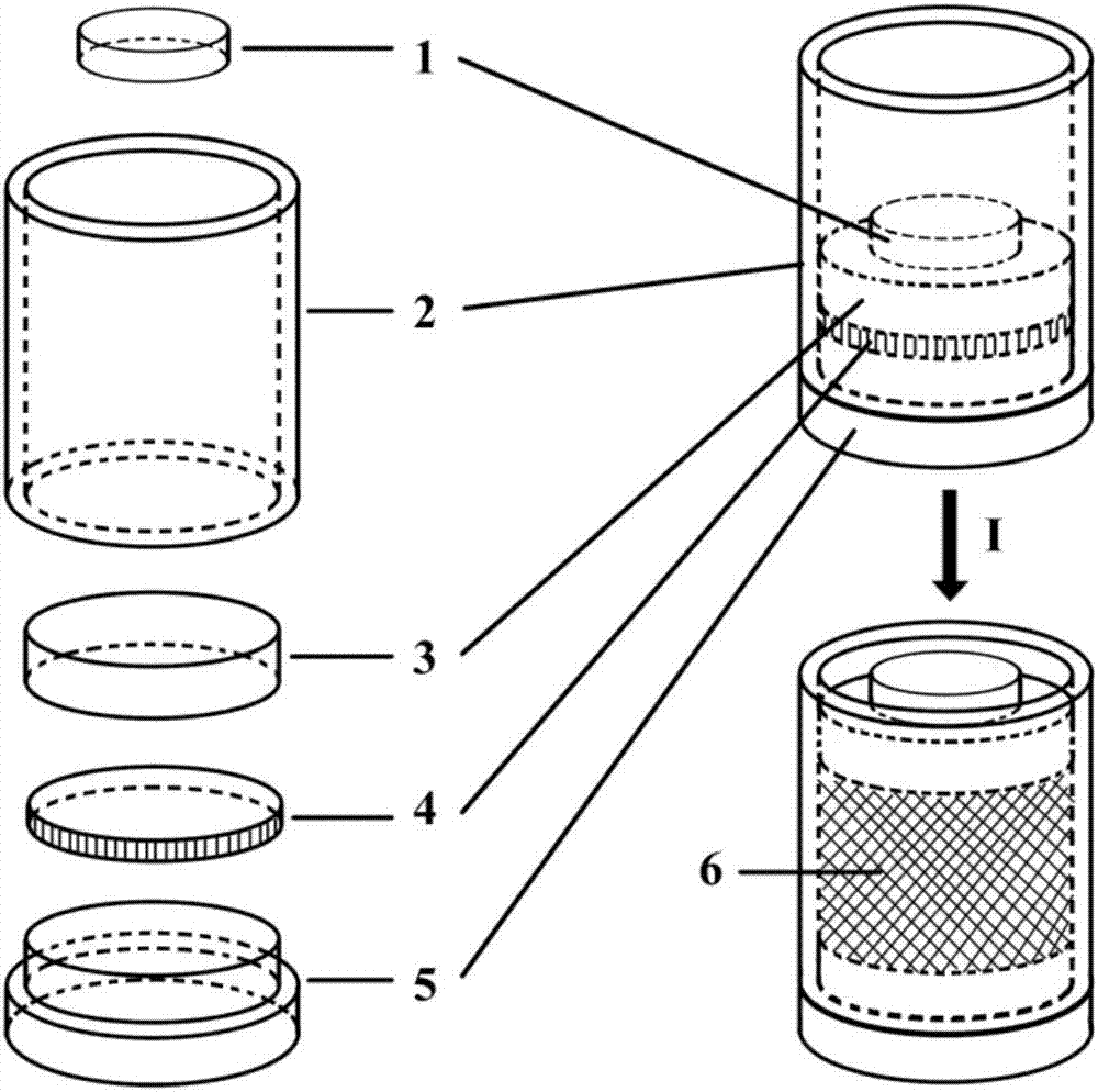
[0045] Prepare the mould, the mold is composed of the bottom plug 5, the lower section and the bottom plug 5 upper section of the ring-shaped jacket 2, the slidable cylindrical piston 3 placed inside the ring-shaped jacket 2 and fitted with the ring-shaped jacket 2, and the press Consists of a weight 1 on a cylindrical piston 3;
[0046] At room temperature, the starch and the mixed acid are uniformly mixed and filtered through suction (preferably vacuum filtration) to obtain the filter cake 4; the filter cake 4 is placed on the bottom plug 5 of the mold, and the lower section of the annular jacket 2 Connect with the upper part of the bottom plug 5, place a cylindrical piston 3 on the filter cake 4, and press a weight 1 on the cylindrical pi...
Embodiment 22
[0057] Embodiment 22: see accompanying drawing.
[0058] A preparation method of thin-walled foamed carbon-carbon nanotube composite material, comprising the following steps:
[0059] a. Preparation of thin-walled foamed carbon:
[0060] Prepare the mould, the mold is composed of the bottom plug 5, the lower section and the bottom plug 5 upper section of the ring-shaped jacket 2, the slidable cylindrical piston 3 placed inside the ring-shaped jacket 2 and fitted with the ring-shaped jacket 2, and the press Consists of a weight 1 on a cylindrical piston 3;
[0061] At room temperature, the starch and the mixed acid are uniformly mixed and filtered through suction (preferably vacuum filtration) to obtain the filter cake 4; the filter cake 4 is placed on the bottom plug 5 of the mold, and the lower section of the annular jacket 2 Connect with the upper section of the bottom plug 5, place a cylindrical piston 3 on the filter cake 4, press a weight 1 on the cylindrical piston 3 t...
Embodiment 23
[0069] Embodiment 23: see accompanying drawing.
[0070] A preparation method of thin-walled foamed carbon-carbon nanotube composite material, comprising the following steps:
[0071] a. Preparation of thin-walled foamed carbon:
[0072] Prepare the mould, the mold is composed of the bottom plug 5, the lower section and the bottom plug 5 upper section of the ring-shaped jacket 2, the slidable cylindrical piston 3 placed inside the ring-shaped jacket 2 and fitted with the ring-shaped jacket 2, and the press Consists of a weight 1 on a cylindrical piston 3;
[0073] At room temperature, the starch and the mixed acid are uniformly mixed and filtered through suction (preferably vacuum filtration) to obtain the filter cake 4; the filter cake 4 is placed on the bottom plug 5 of the mold, and the lower section of the annular jacket 2 Connect with the upper part of the bottom plug 5, place a cylindrical piston 3 on the filter cake 4, and press a weight 1 on the cylindrical piston 3 ...
PUM
| Property | Measurement | Unit |
|---|---|---|
| Diameter | aaaaa | aaaaa |
| Thickness | aaaaa | aaaaa |
| Diameter | aaaaa | aaaaa |
Abstract
Description
Claims
Application Information
 - Generate Ideas
- Intellectual Property
- Life Sciences
- Materials
- Tech Scout
- Unparalleled Data Quality
- Higher Quality Content
- 60% Fewer Hallucinations
Browse by: Latest US Patents, China's latest patents, Technical Efficacy Thesaurus, Application Domain, Technology Topic, Popular Technical Reports.
© 2025 PatSnap. All rights reserved.Legal|Privacy policy|Modern Slavery Act Transparency Statement|Sitemap|About US| Contact US: help@patsnap.com