
Self-power-generation encircling type marine vertical tube vibration monitoring system

A vibration monitoring system and self-generating technology, applied to vibration measurement in solids, electric vehicles, and vibration measurement, etc., can solve the problems of limited power generation effect, inability to realize real-time feedback in the monitoring of riser motion, etc. The effect of reducing the probability, reducing the possibility of destruction, and improving the power generation efficiency

Active Publication Date: 2017-07-25
JIANGSU UNIV OF SCI & TECH
View PDF6 Cites 5 Cited by
  • Summary
  • Abstract
  • Description
  • Claims
  • Application Information

AI Technical Summary

Problems solved by technology

However, the power generation effect of this scheme will be affected by the vibration direction of the standpipe and the direction of incoming flow, and the power generation effect has certain limitations.
Chinese patent application (application number: 201510215304.4) "wing-swing marine riser vortex-induced vibration self-generation monitoring device", because it only stores the monitoring information of the riser movement state in the SD card, the monitoring of the riser movement cannot be realized real-time feedback

Method used


Image

  • Self-power-generation encircling type marine vertical tube vibration monitoring system
  • Self-power-generation encircling type marine vertical tube vibration monitoring system
  • Self-power-generation encircling type marine vertical tube vibration monitoring system

Examples


Embodiment Construction

[0032] The present invention will be described in further detail below in conjunction with the accompanying drawings.

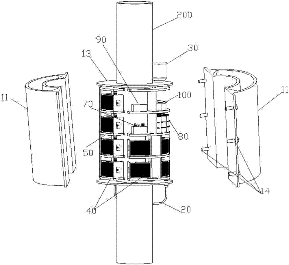
[0033] figure 1 It is a structural schematic diagram with a partial section of an embodiment of the self-generating embracing marine riser vibration monitoring system of the present invention. To better illustrate the internal structure, figure 1 The watertight cavity housing assembly in is disassembled. Such as figure 1 As shown, this embodiment includes: a standpipe 200 , a casing 10 , an underwater acoustic transducer 30 , a power generating device 40 , a rectifier 70 , a battery pack 80 , a step-up transformer 90 and a sensor 100 .

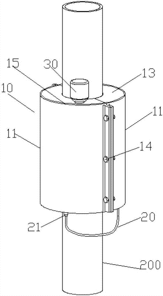
[0034] The adopted watertight housing 10 includes at least two detachable watertight cavity housing components 11, which are fixed on the riser 200 in an encircling manner.

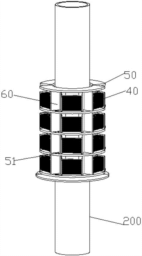
[0035] Each of the detachable cavity shell components 11 is respectively provided with at least two layers of partitions 50; each layer of partition...


PUM


Abstract

The present invention discloses a self-power-generation encircling type marine vertical tube vibration monitoring system. The system comprises a vertical pipe and a shell. The shell comprises at least two watertight cavity shell assemblies, wherein the watertight cavity shell assemblies are fixed on the vertical pipe in the encircling manner. At least two layers of partition boards are respectively arranged inside each watertight cavity shell assembly. A power generation device, a rectifier, a storage battery pack, a boosting transformer and a sensor are arranged on each layer of the partition board in the weight balanced manner. During the vibration of the vertical pipe, the vertical pipe drives the power generation device to generate the alternating current and the alternating current is converted into the direct current through the rectifier to be stored in a storage battery. The current is supplied to the sensor through the boosting transformer. The sensor monitors the motion state of the vertical pipe. An underwater acoustic transducer is placed at the top of the shell and is used for converting a monitored electric signal into an acoustic signal. The acoustic signal is transmitted to an aquatic reception transducer through the water medium to be converted into an electrical signal. According to the technical scheme of the invention, when flows are coming from all directions, the power generation is realized through the vortex-induced vibration of the vertical pipe. Meanwhile, the generated power is supplied to a monitor and monitoring data are automatically sent back to a platform or a base.

Description

technical field [0001] The invention belongs to the technical field of marine engineering equipment, and relates to a marine riser vibration monitoring system, in particular to an encircling marine riser vibration monitoring system capable of generating electricity by itself. Background technique [0002] With the gradual advancement of offshore oil exploitation to deep water, the vortex-induced vibration of marine structures represented by risers has been paid more and more attention. The riser is the main component between the offshore platform and the subsea wellhead, and it is also a component that is relatively easy to damage. When ocean currents and waves of a certain speed flow through the standpipe, alternate vortices will be formed around it, and the shedding of the vortex will generate a periodic alternating force on the standpipe, causing the pipe to generate vortex-induced vibration. In turn, it affects the flow field, making the vortex stronger. When the vorte...

Claims


Application Information

Patent Timeline
Patent Type & Authority Applications(China)
IPC IPC(8): G01H1/00H02J7/32H02K7/18
CPCG01H1/00H02J7/32H02K7/1876
Inventor 姚震球郭琦
Owner JIANGSU UNIV OF SCI & TECH
Learn More