Porous needle, medicine-dispensing device and medicine-dispensing method

A dispensing device and technology of hole needles, which are applied in the field of medical equipment, can solve problems such as the inability to suck out the liquid medicine, affect the dispensing dose, pollute the environment, etc., and achieve the effects of safe and reliable dispensing efficiency, high dispensing efficiency, and convenient manufacture

Inactive Publication Date: 2017-07-28
CHENGDU JIESHIDE SCIENCE AND TECHNOLOGY CO LTD
View PDF4 Cites 4 Cited by
  • Summary
  • Abstract
  • Description
  • Claims
  • Application Information

AI Technical Summary

Problems solved by technology

[0005] The purpose of the present invention is to overcome the existing vial dispensing device existing in the prior art when extracting the Chinese medicinal liquid in the vial into the syringe, there will be a part of the medicinal liquid in the vial that cannot be sucked clean, which will affect the dosage of the dispensing and cause waste. In view of the above-mentioned shortcomings that improper follow-up treatment may pollute the environment, a porous needle, a dispensing device and a dispensing method are provided

Method used


Image

  • Porous needle, medicine-dispensing device and medicine-dispensing method
  • Porous needle, medicine-dispensing device and medicine-dispensing method
  • Porous needle, medicine-dispensing device and medicine-dispensing method

Examples


Embodiment 1

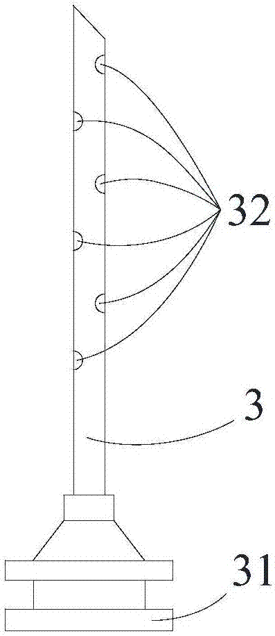
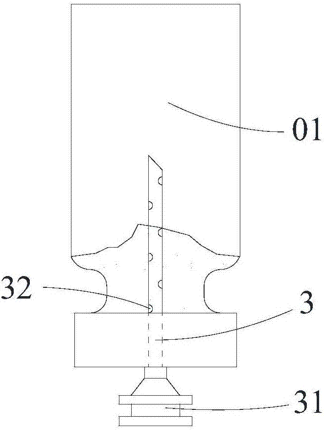
[0062] Such as Figure 1-2 As shown, a porous needle according to the present invention includes a needle tube 3 and a needle handle 31 connected thereto. The wall of the needle tube 3 is provided with at least one hole 32, and the hole 32 closest to the needle handle 31 is The distance to the needle handle 31 is equal to the thickness of the rubber stopper of the vial 01. When in use, the vial 01 is turned upside down, and the porous needle is inserted into the vial 01 from bottom to top.

[0063] As a preferred solution of this embodiment, the end of the needle tube 3 is conical. With this structure, the conical end is convenient for processing and inserting and closing the container cap.

[0064] Using the porous needle of the present invention, when dispensing medicine, the needle tube 3 is inserted into the rubber stopper of the vial 01 until the needle handle 31 touches the outer surface of the rubber stopper. At this time, the holes 32 on the needle tube 3 all enter the...

Embodiment 2

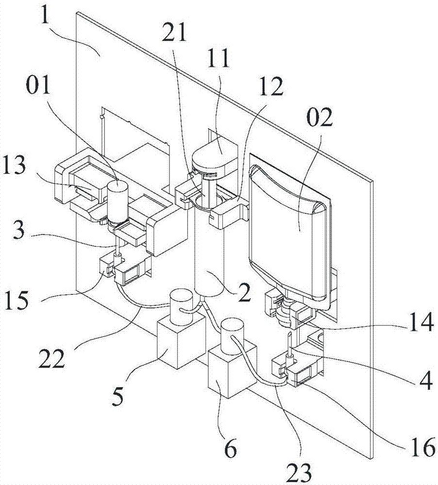
[0066] Such as Figure 1-6 As shown, a drug dispensing device according to the present invention includes a control system and a double-ended syringe 2 arranged on a base 1 .

[0067] The base 1 is provided with a linear reciprocating mechanism 11 that drives the piston rod 21 of the double-ended syringe 2 to move, and the two ends of the double-ended syringe 2 are connected to the first 22 and the second 23 respectively. The other end of conduit one 22 is connected to the porous needle as described in embodiment 1, and the porous needle is used to insert the vial 01, and the other end of conduit two 23 is connected to the needle 4 for inserting the infusion bag 02, and the vial 01 and the infusion bag 02 are set upside down on the base 1, the needle points of the porous needle and the needle 4 are set on the base 1 upward, and the vial 01 and the porous needle can face each other or opposite movement, the infusion bag 02 and the needle 4 can move toward or oppositely, the fi...

Embodiment 3

[0073] Such as Figure 1-7 As shown, a kind of dispensing method of the present invention uses the dispensing device as described in embodiment 2, and its dispensing method comprises the following steps:

[0074] a. Set the vial 01 and the infusion bag 02 upside down on the base 1;

[0075] b. The control system controls the first clamping part 5 and the second clamping part 6 to clamp the first conduit 22 and the second conduit 23 respectively;

[0076] c. The control system controls the vial 01 and the porous needle to move towards each other, the needle tube 3 of the porous needle is inserted into the vial 01, and the handle 31 of the porous needle contacts the rubber of the vial 01 plug, the control system controls the infusion bag 02 and the needle 4 to move toward each other, and the needle 4 is inserted into the infusion bag 02 and contacts the liquid medicine in the infusion bag 02;

[0077] d. The control system controls the clamping part 26 to loosen the conduit 23...


PUM


Abstract

The invention discloses a porous needle. The porous needle comprises a needle tube and a needle handle communicated with the porous needle. At least one hole is arranged in the tube wall of the needle tube; the distance from the hole, closest to the needle handle, to the needle handle is equal to the thickness of a penicillin bottle rubber plug. Utilizing the porous needle, the needle tube is inserted into the penicillin bottle rubber plug until the needle handle contacts with the outer surface of the rubber plug when medicine is dispensed; at that time, holes on the needle tube enter the inside of a penicillin bottle and at least one hole contacts with the rubber plug. Because of the inertia effect when a needle is thrusted and the tension effect when medicine liquid is in the needle body, agentia inside the penicillin bottle does not overflow from the hole in the tube wall. Liquid is injected into the penicillin bottle through the porous needle, and the agentia inside the penicillin bottle is mixed. In the suction process, the medicine liquid is concentrated in the upper part of the rubber plug because the penicillin bottle is placed inversely; finally the sucked medicine liquid is pulled away from the penicillin bottle through the hole located below the liquid level and the hole contacting with the rubber plug. The porous needle has the advantages of being simple in structure, convenient to manufacture, and being capable of fully sucking the medicine liquid in the penicillin bottle.

Description

technical field [0001] The invention relates to the technical field of medical equipment, in particular to a porous needle, a medicine dispensing device and a medicine dispensing method. Background technique [0002] A vial is a small glass container used to hold medicinal liquid. Its structure includes a bottle body and a bottle head, and a bottleneck located in the concave part between the bottle body and the bottle head. The capacity is generally 1-20ml, and it is generally used for injection medicinal liquid Or powder, the bottle cap of the bottle head is generally made of rubber, and a layer of metal aluminum foil is also set outside the rubber to seal. [0003] The patent application with the application number CN201610317078.5 discloses a vial dispensing device and dispensing method, which realizes the automatic dispensing of vials, can effectively avoid the reflux of medicinal liquid, effectively reduces labor intensity, and has high dispensing efficiency, safety and...

Claims


Application Information

Patent Timeline
Patent Type & Authority Applications(China)
IPC IPC(8): A61J1/20A61J1/05
CPCA61J1/2006A61J1/05A61J1/2051A61J1/2055A61J1/2058A61J1/2089A61J1/2096
Inventor 郑永强柏轲
Owner CHENGDU JIESHIDE SCIENCE AND TECHNOLOGY CO LTD
Why Eureka
Try Eureka