capacity control valve

A capacity control and control channel technology, which is applied in the direction of non-electric variable control, fluid pressure control, control/regulation system, etc., can solve the problems of inability and embedding of the valve stem, reduce leakage, improve foreign body resistance, and improve control speed effect

Active Publication Date: 2019-03-12
EAGLE INDS
View PDF6 Cites 0 Cited by
  • Summary
  • Abstract
  • Description
  • Claims
  • Application Information

AI Technical Summary

Problems solved by technology

If the valve stem constituting the sliding surface is inclined with respect to the axis, the gap on the inclined side becomes narrow, and the powder is embedded in the narrower part, so there is a problem that the valve stem cannot operate as set, and improvement is urgently desired.

Method used


Image

  • capacity control valve
  • capacity control valve
  • capacity control valve

Examples


Embodiment 1

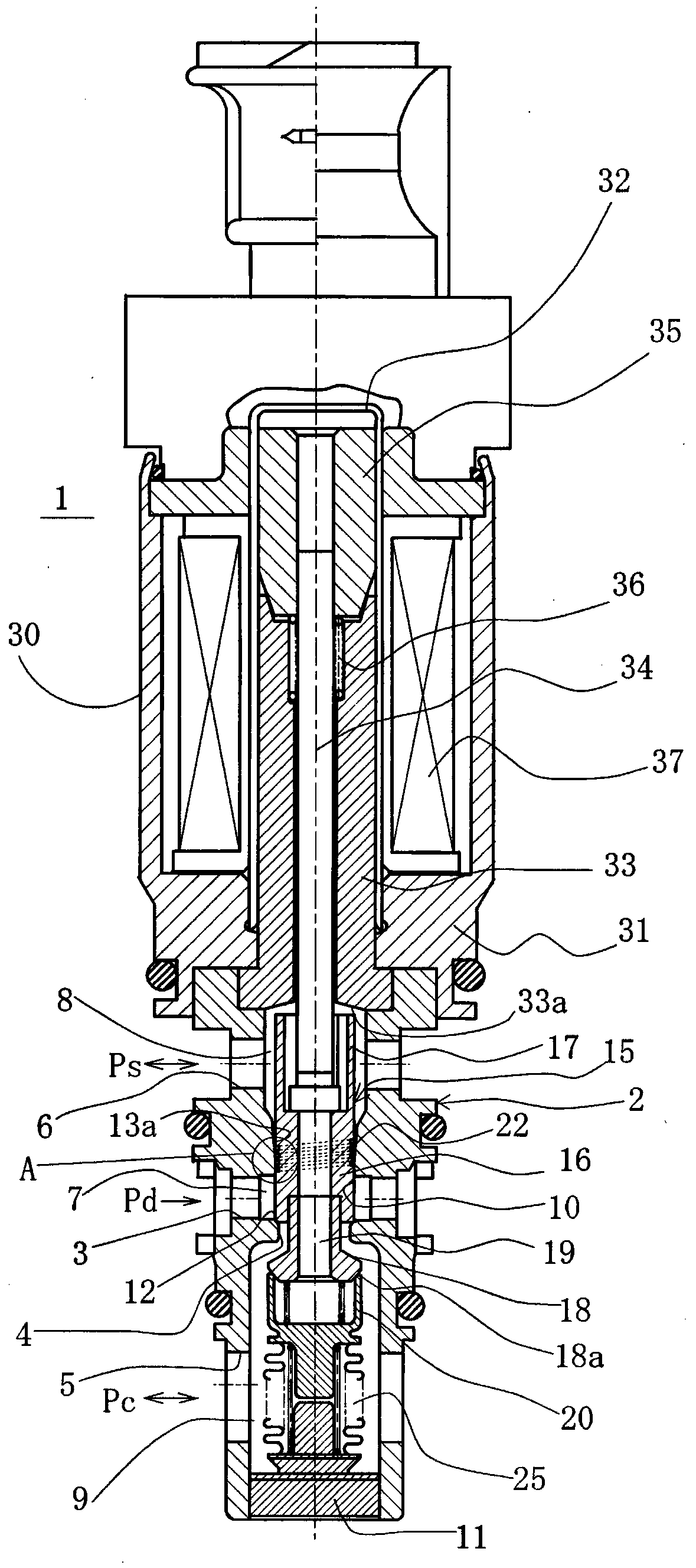
[0032] refer to figure 1 as well as figure 2 , the capacity control valve according to Embodiment 1 of the present invention will be described.

[0033] The capacity control valve 1 includes: a valve case 2 formed of a metal material or a resin material; a valve element 15 disposed in the valve case 2 to reciprocate freely; and a pressure sensitive body 25 that biases the valve element 15 in one direction. and the solenoid 30, etc., which are connected to the valve housing 2 as a driving part for applying an electromagnetic driving force to the spool 15.

[0034] The solenoid 30 includes: a housing 31 connected to the valve housing 2 and formed of a metal material; a sleeve 32 with one end closed; a cylindrical fixed iron core 33 arranged inside the housing 31 and the sleeve 32; The inner side of the fixed iron core 33 is free to reciprocate and the driving rod 34 whose front end is connected with the valve core 15; the movable iron core 35 fixed on the other end side of t...


PUM


Abstract

The invention significantly improves the discharge function of the foreign matter intruded between the outer peripheral surface of the valve core and the inner peripheral surface of the main body and the centering function of the valve core. A capacity control valve (1) is provided with a valve housing (2), a spool (15) that is installed in a guide passage (10) of the valve housing (2) to open and close the control passage, and a spool (15) for opening and closing the control passage. ) a solenoid (30) for on-off driving, characterized in that a tapered portion ( 13a) and a helical groove (22) is provided on the other side, and the tapered part (13a) is set to be between the outer peripheral surface (15a) of the valve core (15) and the guide surface (10a) of the guide passage (10). The gap is larger on the low-pressure side than on the high-pressure side, and the tapered part (13a) and the spiral groove (22) are set so that, in the entire range from the start point to the end point of the stroke of the spool (15), the taper part (13a) The starting point (14) is located in the region of the helical groove (22).

Description

technical field [0001] The present invention relates to a capacity control valve for variably controlling the flow rate or pressure of a working fluid, for example, a capacity control valve for controlling the discharge rate of a variable capacity compressor used in an air-conditioning system such as an automobile according to a pressure load . Background technique [0002] The displacement control valve controls, for example, the control fluid that operates in the variable displacement compressor and the discharge fluid that is supplied by opening and closing the valve. Iron powder and aluminum powder generated by abrasion during internal operation of the variable capacity compressor are mixed in this discharge fluid. Since the diameter of this powder is about 10 μm, it adheres between the sliding surfaces of the capacity control valve. If the valve stem constituting the sliding surface is inclined with respect to the axis, the gap on the inclined side becomes narrow, and...

Claims


Application Information

Patent Timeline
Patent Type & Authority Patents(China)
IPC IPC(8): F16K31/06F16K51/00
CPCF04B27/1009F04B39/10F04B2027/1813F04B2027/1827F04B2027/1845F04B2027/185F04B2027/1854F16K25/04F16K27/029F16K41/00F16K47/12F16K51/00F04B27/1804F16K31/06G05D16/2024F16K1/36F16K1/42F16K31/0655F16K31/0675F16K47/06
Inventor 叶山真弘东堂园英树二口雅行福留康平
Owner EAGLE INDS
Why Eureka
Try Eureka