Hydraulic screwup control device and method of skin-pass mill

A technology of control device and hydraulic control valve, which is applied in the direction of fluid pressure actuation device, contour control, mechanical equipment, etc., can solve the problems of energy waste in pumping station, complicated design of hydraulic pressure control device, and high system design cost, so as to reduce the Spare parts consumption and the effect of reducing work energy consumption and simplifying design

Inactive Publication Date: 2017-08-04
ANGANG STEEL CO LTD
View PDF8 Cites 6 Cited by
  • Summary
  • Abstract
  • Description
  • Claims
  • Application Information

AI Technical Summary

Problems solved by technology

The design of the hydraulic pressure control device of the cold calendering machine is relatively complicated. The hydraulic pressure control device is controlled by a hydraulic pump in a pump station. When the pressure cylinder is quickly opened or closed, the use of low pressure and large flow can meet the requirements. During the production process The medium-pressure upper cylinder uses high pressure and small flow rate. Because it is controlled by a high-pressure pump station, unnecessary energy waste is caused by the pump station during work.
And due to the complicated design of the hydraulic pressure control device, the system design cost is high

Method used


Image

  • Hydraulic screwup control device and method of skin-pass mill
  • Hydraulic screwup control device and method of skin-pass mill

Examples


Embodiment Construction

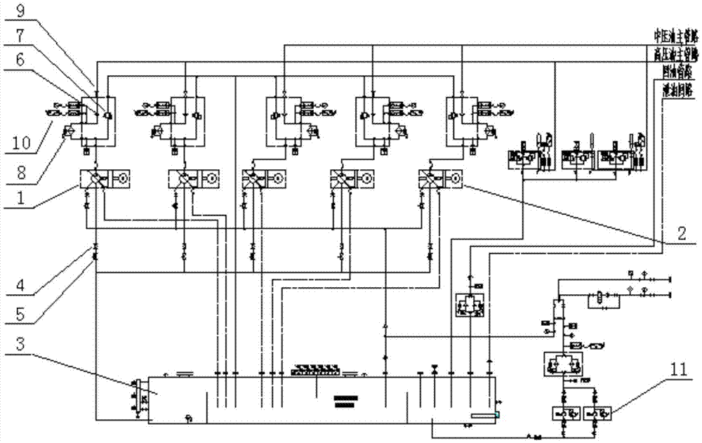
[0020] The hydraulic press-up control device of the skin pass machine of the present invention is composed of a hydraulic pump station and a hydraulic control valve table.

[0021] The hydraulic pump station is equipped with 2 high-pressure pumps 1, 3 medium-pressure pumps 2 and an oil tank 3. The 2 high-pressure pumps 1 are connected in parallel. Master Road. The three medium-pressure pumps 2 are connected in parallel, the medium-pressure pump 2 is connected with the small valve block of the outlet by rubber hose, and the small valve block is connected to the main medium-pressure oil pipeline through a stainless steel high-pressure steel pipe. The inlet side of the high-pressure pump 1 and the medium-pressure pump 2 are equipped with stop valve Ⅰ4 and damping throat 5, and the shut-off valve Ⅰ4 and damping throat 5 are connected in series on the suction pipeline; the outlet sides of high-pressure pump 1 and medium-pressure pump 2 are equipped with single Directional valve I6...


PUM


Abstract

The invention provides a control device and method for hydraulic pressure on a skin pass machine. The control device is composed of a hydraulic pump station and a hydraulic control valve table; the hydraulic pump station is equipped with 2 high-pressure pumps and 3 medium-pressure pumps; the high-pressure pump and the medium-pressure pump The inlet side is connected to the suction pipe in series through a stop valve and damping throat, and the outlet side is equipped with a check valve, overflow valve, filter, stop valve and pressure switch. The hydraulic control valve table includes a dynamic control adjustment circuit for the upper cylinder, a quick opening or closing control circuit for the upper cylinder, and a rod cavity control circuit for the upper cylinder. The high-pressure oil pipeline of the hydraulic control valve table is connected to the oil circuit of the high-pressure pump station to form a dynamic control adjustment of the upper cylinder; the medium-pressure oil pipeline of the hydraulic control valve table to quickly open and quickly close the circuit is connected to the medium-pressure pump station to form a pressure upper cylinder Quick action. The invention can save a hydraulic pump, correspondingly reduce the working energy consumption of the hydraulic pump and related hydraulic components, and reduce the consumption of spare parts and the operation cost of the skin-passing machine.

Description

technical field [0001] The invention belongs to the technical field of cold rolling process equipment, and in particular relates to a hydraulic pressing control device and a control method for a cold rolling mill. Background technique [0002] The main function of the cold rolling mill is to realize the strip shape and performance control, which is an important link in the strip production process. The hydraulic pressing control device of the skin pass mill is an important part of the work of the skin pass mill, and its working performance has a great influence on the production process of the strip steel. The design of the hydraulic pressure control device of the cold calendering machine is relatively complicated. The hydraulic pressure control device is controlled by a hydraulic pump in a pump station. When the pressure cylinder is quickly opened or closed, the use of low pressure and large flow can meet the requirements. During the production process The medium-pressure ...

Claims


Application Information

Patent Timeline
Patent Type & Authority Applications(China)
IPC IPC(8): F15B11/17F15B1/02B21B37/28
CPCF15B11/167B21B37/28F15B1/02F15B11/17
Inventor 杨忠杰商融廉法勇柳军马志洋庞旭孔伟东李富强杨军荣韩炯
Owner ANGANG STEEL CO LTD
Why Eureka
Try Eureka