
Waste gas treatment device of pre-roll-coating aluminum roll production line

A technology of waste gas treatment device and production line, which is applied in the directions of air quality improvement, combustion method, lighting and heating equipment, etc., can solve the problems of increased maintenance expenditure of user units, insufficient combustion of waste gas, high maintenance cost, and achieve good thermal insulation effect. , Improve the utilization rate and protect the environment

Active Publication Date: 2017-08-15
山东中创新材料科技有限公司
View PDF6 Cites 2 Cited by
  • Summary
  • Abstract
  • Description
  • Claims
  • Application Information

AI Technical Summary

Problems solved by technology

[0003] The invention patent with the authorized notification number CN103994449B discloses a composite exhaust gas treatment device, including a photocatalytic oxidation device, an activated carbon adsorption device, a heat storage furnace and a chimney. The three parts are connected in sequence through a gas pipeline, and the activated carbon adsorption device and A flame arrester is installed between the regenerative furnaces, and an induced draft fan is installed between the regenerative furnaces and the chimney; the activated carbon adsorption device used can only handle low-temperature and low-flow exhaust gas, and the later maintenance costs are high, which increases the maintenance of the user unit In addition, the waste heat generated by the combustion of the waste gas is discharged to the outside through the chimney, resulting in a waste of energy, and the incomplete combustion of the waste gas will also pollute the environment

Method used


Image

  • Waste gas treatment device of pre-roll-coating aluminum roll production line
  • Waste gas treatment device of pre-roll-coating aluminum roll production line
  • Waste gas treatment device of pre-roll-coating aluminum roll production line

Examples


Embodiment 1

[0034] Such as Figure 1-7 as shown,

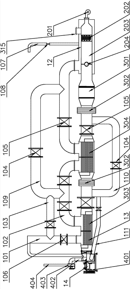
[0035] An exhaust gas treatment device for a pre-roll coating aluminum coil production line, including a combustion system 12, a heat exchange system 13, and a spray drying system 14, and the spray drying system 14 includes a spray drying box 401, a clean air outlet 402, and an induced draft fan 403 , Exhaust flue 404, described spray drying case 401 upper side is provided with net gas outlet 402, and described net gas outlet 402 side is provided with induced draft fan 403, and described induced draft fan 403 and net air outlet 402 pass pipeline Connected, the side of the induced draft fan 403 is provided with an exhaust flue 404;

[0036] One side of the spray drying system 14 is provided with a heat exchange system 13, the heat exchange system 13 includes a regenerator 301, a primary heat exchanger 303, and a secondary heat exchanger 304, and the spray drying box 401- There is a primary heat exchanger 303 on the side, and the primary ...

Embodiment 2

[0043] Such as Figure 8 as shown,

[0044]The difference from Embodiment 1 is that a first bypass pipe 103 is provided on one side of the waste gas inlet pipe 101, a bypass pipe valve 104 is provided on the first bypass pipe 103, and a bypass pipe valve 104 is provided on the first bypass pipe 101. 103 is connected to the exhaust gas outlet 306 of the primary heat exchanger 303 and the main pipeline 102. When the primary heat exchanger 303 fails, close the exhaust gas inlet valve 106, open the bypass pipeline valve 104 on the first bypass pipeline 103, and the flue gas Bypass the primary heat exchanger 303 and directly enter the next processing procedure, providing conditions for maintenance personnel to repair the primary heat exchanger 303, avoiding system shutdown caused by the failure of the primary heat exchanger 303, reducing the probability of system shutdown, and indirectly The economic loss caused by system shutdown is greatly reduced. The heat and flue gas generate...

Embodiment 3

[0046] Such as Figure 9-10 as shown,

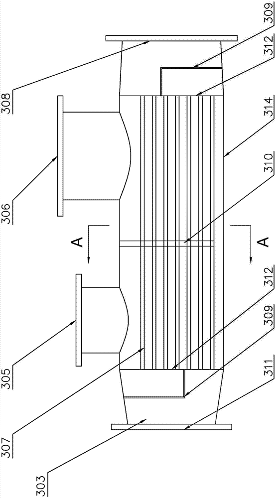
[0047] The difference from Embodiment 1 and Embodiment 2 is that a second bypass pipe 109 is provided on the side of the main pipe 102 of the waste gas outlet 306 of the primary heat exchanger 303, and a bypass pipe 109 is provided on the second bypass pipe 109. Through the pipeline valve 104, the second bypass pipeline 109 is connected to the main pipeline 102 of the waste gas outlet 306 of the secondary heat exchanger 304, and the hot clean gas inlet 308 and the hot clean gas outlet 311 of the secondary heat exchanger 304 pass through the third The bypass pipeline 110 is connected, and the third bypass pipeline 110 is provided with a bypass pipeline valve 104; when the secondary heat exchanger 304 breaks down, close the main pipeline valve 105 at the waste gas inlet 305 of the secondary heat exchanger 304 and the main pipeline valve 105 at the waste gas outlet 306, open the bypass pipeline valve 104 on the second bypass pipeline 109 a...


PUM


Abstract

The invention discloses a waste gas treatment device of a pre-roll-coating aluminum roll production line. The waste gas treatment device of the pre-roll-coating aluminum roll production line comprises a combustion system, a heat exchange system and a spray drying system. The spray drying system comprises a spray drying tank, a clean air outlet, an induced draft fan and an exhaust flue. The heat exchange system is arranged on one side of the spray drying system and comprises a heat accumulation chamber, a primary heat exchanger and a secondary heat exchanger. The combustion system is arranged on one side of the heat accumulation chamber and comprises a combustion engine, a mixer, a combustor and a fireproof plate. By adoption of the primary heat exchanger and the secondary heat exchanger, waste heat generated after combustion of waste gas is reused, on the one hand, preheating is conducted before combustion of the waste gas, so that the combustion efficiency of the waste gas is improved, and on the other hand, heat is provided for the spray drying tank, consumption of energy is reduced, the utilization rate of energy is improved, and protection on the environment is achieved.

Description

technical field [0001] The invention belongs to the technical field of pre-roller-coated aluminum coil production, and particularly relates to a waste gas treatment device for a pre-roller-coated aluminum coil production line. Background technique [0002] The coating process of aluminum coils includes the following steps: unwinding, pre-degreasing, water washing, degreasing, water washing, passivation, drying, primer, coating, one-zone baking, two-zone baking, three-zone baking, cooling , fine coating, film coating, and material collection; according to the coating production process, the coating exhaust gas mainly comes from the pretreatment, spraying, and drying processes, and the pollutants discharged are mainly: dust or acid mist generated during the pretreatment process, spray paint The paint mist and organic solvents generated during drying and volatilization; the paint mist mainly comes from the part of the solvent-based paint scattered in the air spraying operation,...

Claims


Application Information

Patent Timeline
Patent Type & Authority Applications(China)
IPC IPC(8): F23G7/07F23J15/06F23L15/00
CPCF23G7/07F23G2209/14F23J15/06F23L15/00Y02A50/20Y02E20/34
Inventor 王东彭勇
Owner 山东中创新材料科技有限公司
Learn More