
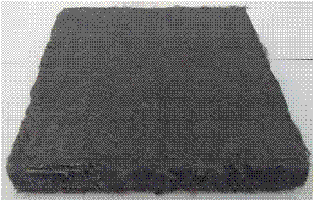
Method for manufacturing high thermal conductivity pitch-based carbon fiber composite material prefabricated body

A pitch-based carbon fiber, composite material technology, applied in heating/cooling fabrics, non-woven fabrics, textiles and papermaking, etc., can solve the problems of non-woven, fiber slippage, and limited size of special-shaped parts, and achieve easy dredging and Conduction, body shape complete and compact, the effect of increasing carbon content

Active Publication Date: 2017-08-18
HUNAN UNIV
View PDF8 Cites 16 Cited by
  • Summary
  • Abstract
  • Description
  • Claims
  • Application Information

AI Technical Summary

Problems solved by technology

But there are the following deficiencies: first, when forming special-shaped parts, it is difficult or even impossible to form due to the limitations of molds and hot pressing conditions; moreover, the requirements for grasping the pressure and the timing of pressurization are relatively high. If the control is not good, fiber slippage will occur. Defects such as shifting and delamination
Feng Zhihai mentioned in the article "Preparation of High Thermal Conductivity Carbon / Carbon Composite Materials" that the use of unidirectional high thermal conductivity pitch-based carbon fibers is hard-woven into a three-dimensional braid. Disadvantages such as inability to weave
[0005] According to comprehensive analysis, in the existing forming methods for high thermal conductivity pitch-based carbon fiber composite preforms, in order to consider the small shrinkage rate, the weaving of raw materials is carried out with graphitized finished fibers, which is difficult or even impossible to form, and is not suitable for mass industrial production. , can not realize the model application, which seriously hinders the improvement of the overall level of military aircraft

Method used


Image

  • Method for manufacturing high thermal conductivity pitch-based carbon fiber composite material prefabricated body
  • Method for manufacturing high thermal conductivity pitch-based carbon fiber composite material prefabricated body

Examples


Embodiment 1

[0030] This embodiment is a specific implementation of the present invention, specifically the following steps:

[0031] (1) Prepare a unidirectional non-woven fabric with a diameter of 5 μm and a 0.1K high thermal conductivity pitch-based pre-oxidized wire, with a thickness of 0.2 mm and an area density of 50 g / m 2 , forming a continuous layer; cut the PAN-based carbon fiber pre-oxidized wire into 20mm, and comb it into a pre-oxidized wire mesh tire with a carding machine, with a thickness of 0.05mm and an area density of 15g / m 2 ;The two are stacked continuously and alternately, and the angle between no weft cloth is 0° / 0°, wherein the weight ratio of the continuous layer to the mesh layer is 60:40, and K represents the number of thousands of tows;

[0032] (2) Introduce Z-direction fibers in the axial direction of the short-fiber mesh tire and the continuous non-woven fabric lay-up through the needling technology, and the needling density is controlled at 10 needles / cm 2 ,...

Embodiment 2

[0037] (1) The 2K high thermal conductivity pitch-based carbon fiber with a diameter of 20 μm and a low-temperature carbonization treatment at 400 °C was prepared into a unidirectional non-woven fabric with a thickness of 0.3 mm and an area density of 200 g / m 2, to form a continuous layer; cut the PAN carbon fiber pre-oxidized wire into 70mm, and comb it into a pre-oxidized wire mesh tire with a carding machine, with a thickness of 0.3mm and a surface density of 90g / m 2 ;The two are continuously and alternately laminated, and the angle between no weft cloth is 0° / 0°, and the weight ratio of continuous carbon fiber to net tire is 80:20;

[0038] (2) Introduce axial fibers through the needle punching technology in the axial direction of the short fiber mesh tire and the continuous non-woven fabric layup, and the needle punching density is controlled at 20 needles / cm 2 , made with a bulk density of 0.50g / cm 3 The quasi-three-dimensional prefabricated body blank;

[0039] (3) Pu...

Embodiment 3

[0041] (1) The 12K high thermal conductivity pitch-based carbon fiber with a diameter of 100 μm and a low-temperature carbonization treatment at 400 °C was prepared into a unidirectional non-woven fabric with a thickness of 0.5 mm and an area density of 400 g / m 2 ;Cut T700-12KPAN carbon fiber into 150mm, and comb it into pre-oxidized wire mesh tire with a carding machine, with a thickness of 0.5mm and a surface density of 200g / m 2 ;The two are laminated continuously and alternately, the angle between no weft cloth is 0° / 90°, and the weight ratio of continuous carbon fiber to net tire is 95:5;

[0042] (2) Introduce axial fibers through the needle-punching technology in the axial direction of the short-fiber mesh tire and the continuous non-woven fabric layup, and the needle-punching density is controlled at 50 needles / cm 2 , made with a bulk density of 0.75g / cm 3 The quasi-three-dimensional prefabricated body blank;

[0043] (3) Place the preform blank under the protection o...


PUM


Abstract

The invention discloses a method for manufacturing high thermal conductivity pitch-based carbon fiber composite material prefabricated body. The method includes: alternatively stacking pre-oxidized or low-temperature carbonized high thermal conductivity pitch-based carbon fiber continuous layers and viscose glue-based or polyacrylonitrile-based or isotropy pitch-based or high thermal conductivity pitch-based short carbon fiber webs; inducing Z-directional reinforcing fibers in the axial direction of the continuous layers and the web layers through a needle punching technology; the Z-directional reinforcing fibers can get through a Z-directional heat conduction channel, Z-directional dredging and conduction of heat is facilitated, the needle punching density is controlled in 10-50 / cm<2>, and the volume density of a three-directional structure prefabricated blank is 0.25-0.75 g / cm<3>; and carbonization and graphitization treatment is performed on the prefabricated blank. The method can form a large-diameter high thermal conductivity pitch-based carbon fiber special-shaped blank, and the forming size and shape are not limited; and the method can manufacture high thermal conductivity pitch-based carbon fiber composite materials, and is suitable for batch industrial production.

Description

technical field [0001] The invention belongs to the technical field of prefabricated material preparation of high thermal conductivity and ablation-resistant carbon / carbon, carbon / ceramic and related composite materials in the thermal management system of military aircraft, and specifically relates to a high thermal conductivity asphalt-based carbon fiber needle-punched quasi-three-way integral structure prefabrication method of making the body. Background technique [0002] Thermal conductivity (λ) can be expressed by Debye formula: λ=1 / 3C·V·L, where C is the heat capacity per unit volume, V is the propagation velocity of phonons, and L is the mean free path of phonons. For carbon (graphite) materials with a relatively complete graphite structure, the room temperature heat conduction rate is mainly determined by the mean free path L of phonons, and L is related to the plane size La of graphite crystallites. The larger La is, the larger L is, and λ higher. Yuan Guanming me...

Claims


Application Information

Patent Timeline
IPC IPC(8): D04H1/4242D04H1/74D04H1/46D06C7/04C04B35/83C04B35/80
CPCC04B35/80C04B35/83C04B2235/5248C04B2235/5252C04B2235/526C04B2235/5268C04B2235/77D04H1/4242D04H1/46D04H1/74D06C7/04
Inventor 李轩科李保六黄东刘洪波刘金水
Owner HUNAN UNIV
Learn More