System used for coal-fired power plant waste-heat utilization and desulfuration water saving

A technology for coal-fired power plants and waste heat, applied in preheating, steam application, feed water heaters, etc., can solve problems such as the limitation of heat exchange effect, achieve the effects of optimizing unit operation, increasing flue gas flow resistance, and fully utilizing waste heat

Pending Publication Date: 2017-08-18
DATANG ENVIRONMENT IND GRP
View PDF7 Cites 2 Cited by
  • Summary
  • Abstract
  • Description
  • Claims
  • Application Information

AI Technical Summary

Problems solved by technology

However, after the flue gas enters the absorption tower, the temperature drops sharply in a short period of time, which limits the heat exchange effect of the device.

Method used


Image

  • System used for coal-fired power plant waste-heat utilization and desulfuration water saving
  • System used for coal-fired power plant waste-heat utilization and desulfuration water saving

Examples


Embodiment 1

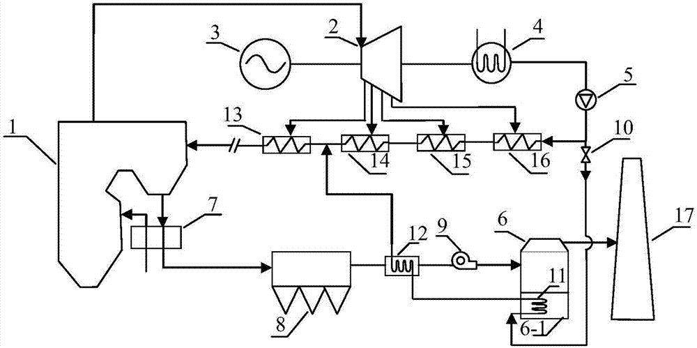
[0031] Example 1, such as figure 1 As shown, what is described in the first embodiment of the present invention is a system for waste heat utilization and desulfurization and water saving in coal-fired power plants. The system includes:

[0032] Steam turbine 2, its intake end is connected to boiler 1, the exhaust gas output end of steam turbine 2 is connected to the intake end of condenser 4, the high-temperature and high-pressure water vapor generated by boiler 1 enters steam turbine 2, and the high-temperature and high-pressure water vapor passes through steam turbine 2 After the energy conversion is completed, the final exhausted gas enters the condenser 4 for cooling and condensation to be converted into condensed water.

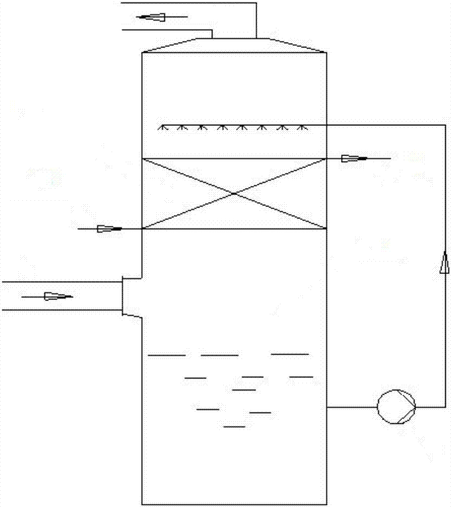
[0033] The primary heat exchanger 11 is arranged in the absorption tower slurry pool 6-1 at the bottom of the desulfurization absorption tower 6, and the condensed water in the primary heat exchanger 11 is heated once by using the temperature of the sl...

Embodiment 2

[0043] Embodiment 2, a waste heat utilization and desulfurization water-saving method for a coal-fired power plant waste heat utilization and desulfurization water-saving system described in the second embodiment of the present invention is:

[0044] The high-temperature and high-pressure water vapor generated by the boiler 1 enters the steam turbine 2, and the steam turbine 2 rotates to drive the generator 3 to generate electricity;

[0045] At the same time, the high-temperature flue gas generated by the boiler 1 enters the air preheater 7 to preheat the air, and then enters the dust collector 8 to remove dust and become medium-temperature flue gas;

[0046] The exhaust gas of the steam turbine enters the condenser 4 to condense to form condensed water, and the condensed water passes through the condensed water pump 5;

[0047] Part of the condensed water flows through the eighth-stage low-pressure heater 16, the seventh-stage low-pressure heater 15, the sixth-stage low-pres...


PUM


Abstract

The invention discloses a system used for coal-fired power plant waste-heat utilization and desulfuration water saving. The system comprises a steam turbine, a first-level heat exchanger, a second-level heat exchanger, a condensate pump and an air pre-heater. The air inlet end of the steam turbine is connected with a boiler, and the exhaust air output end of the steam turbine is connected with the air inlet end of a condenser. The first-level heat exchanger is arranged in an absorption tower slurry pond at the bottom of a desulfuration absorption tower. The second-level heat exchanger is arranged between the desulfuration absorption tower and a dust remover, and the liquid inlet end of the second-level heat exchanger is connected with the liquid outlet end of the first-level heat exchanger. The liquid outlet end of the second-level heat exchanger is connected with an inlet pipeline of a fifth-level low-pressure heater. The air outlet end of the dust remover is connected with the air inlet end of the second-level heat exchanger. An outlet pipeline of the fifth-level low-pressure heater is connected with the boiler. The liquid inlet end of the condensate pump is connected with the liquid outlet end of the condenser, and the liquid outlet end of the condensate pump is connected with the first-level heat exchanger. The air inlet end of the air pre-heater is connected with the boiler, and the air outlet end of the air pre-heater is connected with the air inlet end of the dust remover.

Description

technical field [0001] The invention relates to the field of energy saving and emission reduction in coal-fired power plants, in particular to a system for waste heat utilization and desulfurization and water-saving in coal-fired power plants. Background technique [0002] The flue gas temperature of the coal-fired power plant entering the desulfurization absorption tower is usually above 90°C to 110°C, and the flue gas contains a lot of waste heat. After the flue gas with higher temperature enters the desulfurization absorption tower, it exchanges heat with the slurry droplets with lower temperature. The water in the slurry evaporates in large quantities and flows out of the absorption tower with the flue gas, and is finally discharged into the atmosphere. In this process, the waste heat of the flue gas has not been effectively utilized, and a large amount of slurry has been evaporated, wasting precious water resources. Under the background of energy saving and emission re...

Claims


Application Information

Patent Timeline
Patent Type & Authority Applications(China)
IPC IPC(8): F22D1/36F01K17/02F01D15/10B01D53/18
CPCB01D53/1481B01D53/18F01D15/10F01K17/02F22D1/36B01D2258/0283
Inventor 蔡子嘉杨春雨徐岩李雯
Owner DATANG ENVIRONMENT IND GRP
Why Eureka
Try Eureka