
Square wave injected method for estimating rotor position, after time delay compensation, of permanent magnet synchronous motor (PMSM)

A permanent magnet synchronous motor, rotor position estimation technology, applied in the control of generators, motor generator control, control of electromechanical transmission devices, etc., can solve the problem of aggravating the influence of position estimation accuracy, position estimation error, sampling point distortion, etc. Achieve the effect of reducing the response current distortion rate, improving the position estimation accuracy, and increasing the bandwidth of the control system

Active Publication Date: 2017-08-22
NORTHWESTERN POLYTECHNICAL UNIV
View PDF4 Cites 26 Cited by
  • Summary
  • Abstract
  • Description
  • Claims
  • Application Information

AI Technical Summary

Problems solved by technology

[0003] At present, the research on the position sensorless control of permanent magnet synchronous motors at home and abroad mainly focuses on the case of high switching frequency, and the elimination of signal delay in the pulse generation link at low switching frequency is realized by redesigning the current controller. The effective decoupling of stator current magnetization component and torque component does not analyze the influence of PWM signal lag and current coupling degree on position estimation accuracy
[0004] The traditional high-frequency injection method at low switching frequency will have the following two special problems: 1) The sinusoidal signal will be severely distorted due to too few sampling points at low sampling frequency, resulting in serious distortion of the high-frequency response signal
2) The PWM signal lags, and as the motor speed increases, the cross-coupling intensifies, which further affects the sine degree of the high-frequency response current envelope, resulting in position estimation errors

Method used


Image

  • Square wave injected method for estimating rotor position, after time delay compensation, of permanent magnet synchronous motor (PMSM)
  • Square wave injected method for estimating rotor position, after time delay compensation, of permanent magnet synchronous motor (PMSM)
  • Square wave injected method for estimating rotor position, after time delay compensation, of permanent magnet synchronous motor (PMSM)

Examples


Embodiment Construction

[0057] Now in conjunction with embodiment, accompanying drawing, the present invention will be further described:

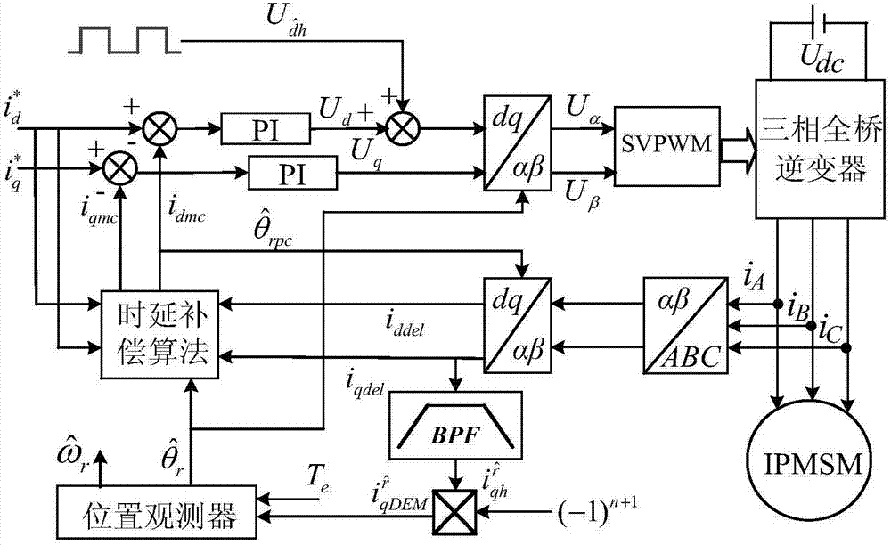
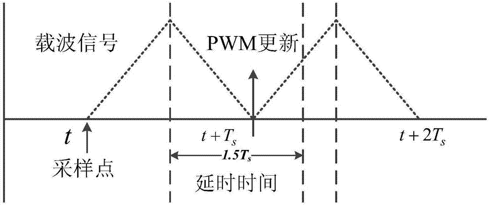
[0058] The present invention is a position sensorless control strategy that realizes the position estimation of permanent magnet synchronous motor through square wave voltage injection. Considering the PWM signal hysteresis caused by low switching frequency and the position estimation error caused by the reduction of injected harmonic frequency, through the analysis of low The hysteresis mechanism of PWM signal at switching frequency and the influence of delay on system stability, a time delay compensation algorithm is proposed, and a position sensorless closed-loop control model suitable for low switching frequency is established, aiming at realizing the magnetization component of stator current Effective decoupling of torque and torque components, thereby improving the response current distortion rate at low switching frequencies and improving the accuracy of po...


PUM


Abstract

The invention relates to a square wave injected method for estimating the rotor position, after time delay compensation, of a PMSM. A PI current regulator controls the magnitudes of output Ud and Uq voltage vectors, square-wave voltage signals are injected to an estimation d axis when the motor is static, initial positioning is completed in a closed-loop manner, and an N pole is converged rapidly to the real d axis. After that the motor is started smoothly, that rapid change of a load component in the dynamic process generates a high frequency component is taken into consideration, and thus, the bandwidth of a position observer is limited, the position estimating precision is influenced, a BPF is used to eliminate the high-frequency component of the load, a q-axis high-frequency response current is obtained, and the rotor position and speed are estimated via the position observer. At the same time, high-frequency response current distortion caused by lagging of PWM signals is eliminated on the basis of q-axis current error time-delay compensation algorithm.

Description

technical field [0001] The invention belongs to the technical field of AC motor transmission, and relates to a position sensorless control method of a permanent magnet synchronous motor, in particular to a method for estimating the time delay compensation method of the rotor position of a permanent magnet synchronous motor based on square wave injection, which is a method for controlling the time delay of the rotor position of a permanent magnet synchronous motor at a low switching frequency. Rotor position estimation method for permanent magnet synchronous motor based on square wave voltage injection using space vector pulse width modulation. Background technique [0002] Due to the advantages of high efficiency, high power density and wide speed range, permanent magnet synchronous motors have attracted close attention from the rail transit industry in recent years. Because it is integrated with the traction motor, the harsh environment has always led to a high failure rate...

Claims


Application Information

Patent Timeline
IPC IPC(8): H02P21/18
Inventor 张航刘卫国陈哲张译文
Owner NORTHWESTERN POLYTECHNICAL UNIV
Learn More