Wet treatment process and wet treatment system for PB (particle board) dry tail gas

A technology for dry tail gas and wet treatment, applied in gas treatment, climate sustainability, greenhouse gas capture, etc., to reduce investment, reduce maintenance workload, and improve the effect of foam dust removal

Pending Publication Date: 2017-08-29
GLOBE ENVIRONMENTAL SHANGHAI
View PDF6 Cites 5 Cited by
  • Summary
  • Abstract
  • Description
  • Claims
  • Application Information

AI Technical Summary

Problems solved by technology

[0007] At present, the industry lacks the process and treatment system for effective treatment of PB tail gas

Method used


Image

  • Wet treatment process and wet treatment system for PB (particle board) dry tail gas
  • Wet treatment process and wet treatment system for PB (particle board) dry tail gas
  • Wet treatment process and wet treatment system for PB (particle board) dry tail gas

Examples


Embodiment 1

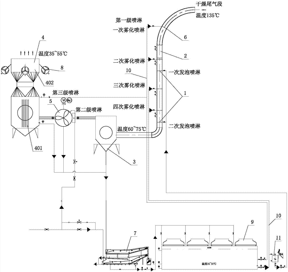
[0165] Such as figure 1 The shown processing system includes atomizing spray cooling pipeline 2 , drip cyclone separator 3 , induced draft fan 5 and exhaust chimney 4 connected in sequence.

[0166] The side wall of the atomizing spray cooling pipeline 2 is provided with a first-stage atomizing spray head 6, and the first-stage spraying includes four atomizing sprays, of which the first two atomizing sprays share one spraying pipeline , the last two atomization sprays share a spray pipeline to ensure that the spray pressure of the four atomization sprays is the same; below the first-stage spray head, there is a foaming nozzle 1, and the foaming spray It includes two foaming sprays, wherein the first foaming spray is located between the second atomized spray and the third atomized spray, and the second foamed spray is located downstream of the fourth atomized spray.

[0167] The drip cyclone separator 3 has a hollow cylindrical shape, and its bottom slag area is connected with...

Embodiment 2

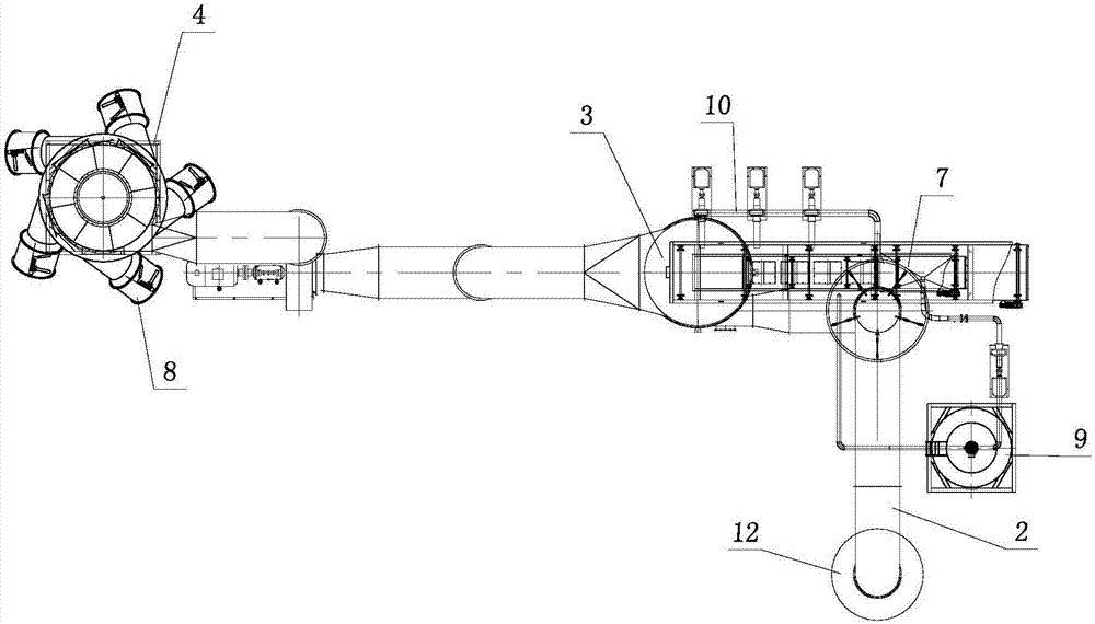
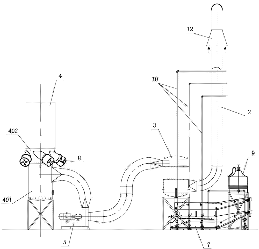
[0184] Such as Figure 2-4 The treatment system shown includes atomizing spray cooling pipeline 2, drip cyclone separator 3, induced draft fan 5 and exhaust chimney 4 connected in sequence, and some pipeline connections are omitted in the figure.

[0185] A conical wind cap 12 is arranged at the inlet of the atomizing spray cooling pipeline 2, the large and small ends of the conical wind cap are oriented in the same direction as the air intake direction of the atomizing spray cooling pipeline 2, and communicated with the atmosphere, and the small end of the conical wind cap is tightly fitted On the atomizing spray cooling pipeline 2 , an air supplement port is provided on the side wall of the atomizing spray cooling pipeline 2 in the small end.

[0186] There are three first-stage spray pipelines 10 on the side wall of the atomization spray cooling pipeline 2, corresponding to three atomization sprays, from top to bottom, the first spray water volume is 100-150m 3 / h, the sec...

Embodiment 3

[0199] Such as Figure 5As shown, the atomization spray cooling pipeline 2 has two sections of Venturi variable-diameter dust removal spray pipeline 201 connected in series. The variable-diameter dust-removing spray pipes 201 are connected by equal-diameter spray pipes 202; the first-stage atomizing spray heads 6 include three atomizing spray heads arranged at intervals along the exhaust gas traveling direction. Venturi variable-diameter dedusting spray pipe 201 corresponds to the variable-diameter pipe high-speed and high-pressure atomization spray cooling zone.


PUM


Abstract

The invention discloses a wet treatment process and a wet treatment system for PB (particle board) dry tail gas. The wet treatment process is implemented by the aid of process regions including a first region which is a high-speed and high-pressure atomizing, spraying and cooling region, a second region which is a medium-temperature flue gas foam dust removal region, a third region which is a water drop cyclone and active dust removal cyclone cooling dust cleaning region, a fourth region which is an active cyclone cooling and air supplementing region, a fifth region which is a slag removal water purification treatment region and a sixth region which is a water circulating cooling region. The wet treatment process and the wet treatment system have the advantages that good dust removal and separation effects can be realized by the wet treatment process and the wet treatment system; water can be recycled after being filtered, and 'white dragon' phenomena can be obviously alleviated during emission; corresponding water vapor can be carried away by supplemented air, and accordingly the problems of incapability of treating 'production wastewater' and necessary increase of huge investment for constructing sewage treatment stations due to a large quantity of condensed water can be solved.

Description

technical field [0001] The invention relates to the field of tail gas treatment for man-made board manufacturing, in particular to a wet treatment process and a treatment system for particle board (PB) drying tail gas. Background technique [0002] At present, the exhaust emission of the wood-based panel production line is basically self-emission, and there is no control on the exhaust gas components. Although there is also an exhaust buffer box for continuous presses, the buffer box mainly passes through the bottom partition to reduce the wind speed and deposit dust. Although this kind of buffer box can deposit some larger particles of dust, most of the dust, especially a large number of tiny dust particles, is still discharged with the exhaust gas, and the buffer box cannot handle other substances in the exhaust gas, especially the man-made substances contained in the exhaust gas. The relatively high concentration of formaldehyde and odor emitted during the board producti...

Claims


Application Information

Patent Timeline
Patent Type & Authority Applications(China)
IPC IPC(8): B01D50/00B01D53/75B01D53/78B01D53/76B01D53/56B01D53/72
CPCB01D50/00B01D53/56B01D53/72B01D53/75B01D53/76B01D53/78B01D2257/708B01D2257/402B01D50/40Y02C20/10
Inventor 黎敏冯杰覃海先
Owner GLOBE ENVIRONMENTAL SHANGHAI
Why Eureka
Try Eureka