UV solidifying method for inner surface of groove body of printed workpiece

A curing method and inner surface technology, applied in the general parts of printing machinery, printing, printing machines, etc., can solve the problems of temperature reduction, inability to use workpieces with grooves, and no solutions are provided, and achieve improved performance. Product quality, wrinkle-free effect

Active Publication Date: 2017-08-29
马鞍山甬兴模塑有限公司
View PDF11 Cites 1 Cited by
  • Summary
  • Abstract
  • Description
  • Claims
  • Application Information

AI Technical Summary

Problems solved by technology

[0005] This solution has a certain effect on the reduction of temperature, but it cannot be used for the processing of workpieces with grooves, and no corresponding solution is given. In order to better realize the processing of workpieces with grooves, it is necessary to Make certain improvements to the existing technology

Method used


Image

  • UV solidifying method for inner surface of groove body of printed workpiece
  • UV solidifying method for inner surface of groove body of printed workpiece
  • UV solidifying method for inner surface of groove body of printed workpiece

Examples


Embodiment 1

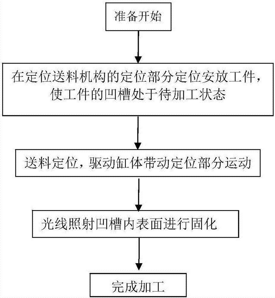
[0044] The invention provides a UV curing method for the inner surface of the tank for printing workpieces, which uses a UV curing device for curing, combined with image 3 , the process is:

[0045] Step 1, positioning the workpiece;

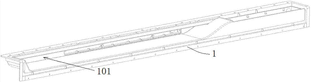
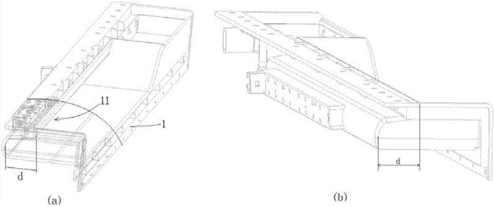
[0046] The workpiece 1 is positioned and placed in the positioning part of the positioning feeding mechanism 3, so that the groove 11 of the workpiece 1 faces the moving direction and is in a state to be processed.

[0047] Step 2, feeding positioning;

[0048] Start the system switch, and the driving cylinder 34 in the moving part of the positioning feeding mechanism 3 drives the positioning part to move, so that the positioning base plate in the positioning part moves to the processing station, and the UV lamp tube in the light curing mechanism is inserted into the groove.

[0049] Moving to the processing station refers to making the UV lamp 42 in the light curing mechanism reach the set position and cooperate with the groove 11; the movem...

Embodiment 2

[0057] combine Figure 4 , Figure 5 , the UV curing device of this embodiment is mainly composed of a support mechanism 2, a positioning feeding mechanism 3 and a light curing mechanism 4. The support mechanism 2 is used to form an integral bracket and form a closed space for light curing.

[0058] Specifically, the support mechanism 2 includes a support frame 21, a top plate 22 and a side wall plate 24. The support frame 21 is a frame structure for supporting other parts. For the required enclosed space, it can be surrounded by the top plate 22 and the side wall plate 24. into, and reserve a feed port for the entry and exit of workpiece 1. The required electric control box 25, switches, etc. can be arranged on the support frame 21, and there is no specific requirement for the specific shape and structure of the support frame 21. The above-mentioned top board and side wall boards are only described in conjunction with the accompanying drawings, and their specific shapes can...

Embodiment 3

[0070] The basic structure of the UV curing device of this embodiment is the same as that of Embodiment 2, the difference being that: the lamp tube support 41 of this embodiment is connected with a cooling water pipe 43, and the cooling water pipe 43 is connected with a circulating water system. This cooling water pipe 43 can be arranged in parallel with the UV lamp tube 42, and is positioned at the cooling water pipe 43 rear, can cool the air in the groove by the cooling water pipe 43, because the cooling water pipe 43 is positioned at the UV lamp tube 42 rear, can not block the light.


PUM


Abstract

The invention discloses a UV solidifying method for the inner surface of a groove body of a printed workpiece and belongs to the technical field of UV solidifying. The UV solidifying method adopts a UV solidifying device for solidifying. According to the solidifying machining process, firstly the workpiece is positioned; the workpiece is positioned and placed on a positioning part of a positioning feeding mechanism, and feeding positioning is executed; a system switch is started, a driving cylinder body in a movement part of the positioning feeding mechanism drives the positioning part to move, and a UV lamp tube in an illuminating solidifying mechanism is inserted into a groove; the UV lamp tube works in the groove, and light rays illuminate the inner surface of the groove to conduct solidifying; and finally the driving cylinder body enables the positioning part to move out of an enclosed space formed by a supporting mechanism to return to an original station, and machining is completed. According to the UV solidifying method for the inner surface of the groove body of the printed workpiece, the UV lamp tube suspending in air is adopted to extend into the groove, the inner surface of the groove is illuminated and solidified, the phenomenon that the inner surface of the groove wrinkles is avoided, and a good using effect is achieved.

Description

technical field [0001] The invention relates to the technical field of UV curing, in particular to a UV curing method for the inner surface of a tank for printing workpieces. Background technique [0002] Ultraviolet light-curing printers have been widely used in the printing industry. After the ink is coated on the paper, it enters the ultraviolet light box for irradiation, and the ink dries and solidifies rapidly under the catalysis of ultraviolet rays. In order to improve the light-curing efficiency, large-scale printing equipment generally needs to use special ink, which is very expensive and expensive. However, the use of ordinary inks cannot achieve the same effect in a short period of time. Increasing the amount of ultraviolet radiation will easily cause the problem of product surface deformation and yellowing. [0003] When processing refrigerator handles, the handle ink needs to be printed and then cured by a large UV curing device. However, since there is a long g...

Claims


Application Information

Patent Timeline
Patent Type & Authority Applications(China)
IPC IPC(8): B41F23/04
CPCB41F23/04
Inventor 陈宏伟
Owner 马鞍山甬兴模塑有限公司
Why Eureka
Try Eureka