Microwave laser radar integrated system

A technology of laser radar and microwave radar, which is applied in the field of microwave detection, can solve the problems that the radar detection system cannot simultaneously achieve high resolution, long detection distance, and is not affected by climate, so as to achieve improved detection performance, large measurement range, and compact structure Effect

Inactive Publication Date: 2017-08-29
HARBIN INST OF TECH
View PDF4 Cites 14 Cited by
  • Summary
  • Abstract
  • Description
  • Claims
  • Application Information

AI Technical Summary

Problems solved by technology

[0003] The present invention aims to solve the problems that the existing radar detection system cannot realize high resolution, long detection distance and no weather influence during the detection process. The present invention provides a microwave laser radar integrated system

Method used


Image

  • Microwave laser radar integrated system
  • Microwave laser radar integrated system
  • Microwave laser radar integrated system

Examples


specific Embodiment approach 1

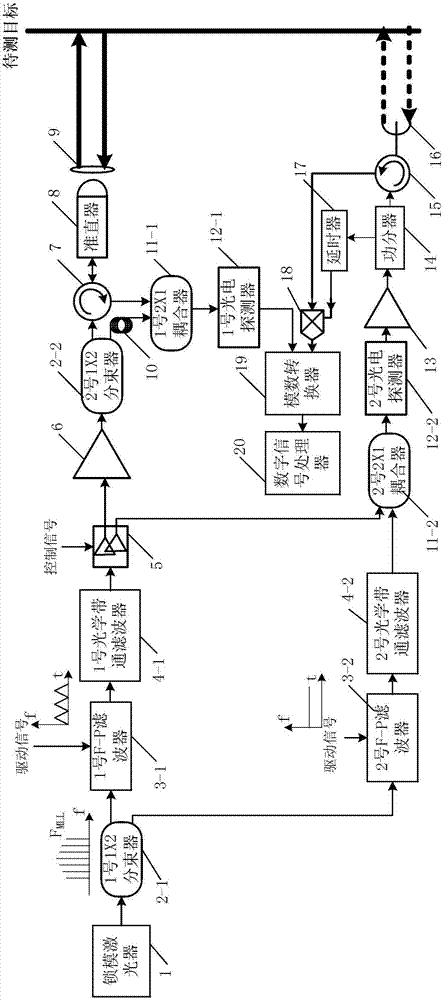
[0042] Specific implementation mode one: see figure 1 Describe this embodiment, the microwave lidar integrated system described in this embodiment, it includes mode-locked laser 1, two 1×2 beam splitters, two F-P filters, two optical bandpass filters, MEMS light Switch 5, fiber amplifier 6, optical circulator 7, collimator 8, transmitting / receiving device 9, delay fiber 10, two 2×1 couplers, two photodetectors, electric amplifier 13, power divider 14 , electric circulator 15, microwave antenna 16, delayer 17, multiplier 18, analog-to-digital converter 19 and digital signal processor 20;

[0043] The two 1×2 beam splitters are respectively defined as No. 1 1×2 beam splitter 2-1 and No. 2 1×2 beam splitter 2-2, and No. 1 1×2 beam splitter 2-1 Output two beams of light with the same light intensity;

[0044] Two F-P filters are respectively defined as No. 1 F-P filter 3-1 and No. 2 F-P filter 3-2;

[0045] The two optical bandpass filters are respectively defined as No. 1 opti...

specific Embodiment approach 2

[0068] Specific implementation mode two: see figure 1 Describe this embodiment, the difference between this embodiment and the integrated microwave lidar system described in Embodiment 1 is that the digital signal processor (20) processes the received data signal, thereby obtaining the The specific process of distance is:

[0069] Step 1: digital signal processor (20) carries out Fourier transform to the received data signal, obtains the frequency spectrum F (I) of intermediate frequency signal,

[0070] Step 2: Extract the spectrum F(I) of the intermediate frequency signal, and the peak frequency f corresponding to the maximum amplitude within the modulation bandwidth range I ,

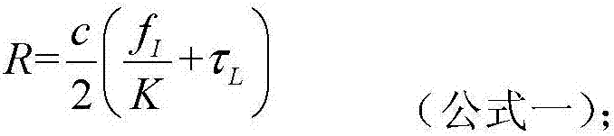
[0071] Step 3: Set the peak frequency f I Substituting into the following formula 1 for calculation, so as to obtain the distance R of the target to be measured;

[0072]

[0073] Said K=2B / T,

[0074] Among them, c represents the speed of light in vacuum, K represents the modulation slope of...

specific Embodiment approach 3

[0075] Specific implementation mode three: see figure 1 Describe this embodiment. The difference between this embodiment and the integrated microwave laser radar system described in Embodiment 1 is that the light output by the No. 1 F-P filter 3-1 is a triangular wave whose longitudinal mode frequency changes linearly with time. Linear Frequency Modulation Signal.


PUM


Abstract

The invention discloses a microwave laser radar integrated system, and belongs to the field of microwave detection. The invention solves problems that a conventional radar detection system cannot achieve high resolution and long detection distance at the same time while the detection process is not affected by the weather. A microwave radar and a laser radar are integrated in one system, so the advantages of the two detection modes are integrated. The system can carry out the flexible switching of the two modes according to different detection environments and different detection requirements, so as to meet the actual demands. The system is large in measurement range, is high in measurement precision, and is wide in application range. Meanwhile, the system employs a common signal modulation and demodulation system, so the system is compact in structure, is high in stability, and is high in flexibility. The system is mainly used for the measurement of the distance of a to-be-measured object.

Description

technical field [0001] The invention belongs to the field of microwave detection. Background technique [0002] In recent years, with the increasingly complex environment and the gradual diversification of the required detection targets, a single detection mode can no longer meet the actual needs. The laser radar has a high detection resolution and can suppress surface clutter, but the laser radar detection system has a short working distance. , and is seriously affected by climate; microwave radar has a long range and is less affected by weather, but microwave radar has low resolution and performance is limited by electronic bottlenecks. Therefore, how to properly combine the two so that they can be better It has become an urgent problem to be solved at present to learn from each other's strengths to meet the higher actual detection requirements. Contents of the invention [0003] The present invention aims to solve the problems that the existing radar detection system c...

Claims


Application Information

Patent Timeline
Patent Type & Authority Applications(China)
IPC IPC(8): G01S13/86G01S13/08G01S17/02G01S17/08
CPCG01S13/08G01S13/865G01S17/08G01S17/86
Inventor 张勇杨成华赵远徐璐刘越豪沈志强邱鹏宇
Owner HARBIN INST OF TECH
Why Eureka
Try Eureka