Fluorinated graphite tubular reactor

A tubular reaction furnace and fluorinated graphite technology, applied in the direction of fluorinated carbon, can solve the problems of gray or even black color of fluorinated graphite, low work efficiency, cumbersome operation, etc., to increase the thickness of graphite layer, improve work efficiency, The effect of high fluorination efficiency

Active Publication Date: 2017-09-05
洛阳森蓝化工材料科技有限公司
View PDF7 Cites 2 Cited by
  • Summary
  • Abstract
  • Description
  • Claims
  • Application Information

AI Technical Summary

Problems solved by technology

The reaction furnace has the following problems: 1) The conversion rate of fluorine gas is not high. Due to the horizontal placement, the fluorine gas passes through the space above the graphite layer and only contacts with the graphite surface layer to cause fluorination reaction.
A considerable part of the fluorine gas does not come into contact with the raw materials, so it is removed from the gas phase space, reducing the conversion rate of fluorine gas
2) The utilization rate of the reaction furnace is not high. Judging from the reaction effect after the fluorination reaction, the color of the fluorinated graphite accumulated on the upper layer is whiter. Since the lower layer cannot be contacted or has less contact with fluorine gas, the color of the generated fluorinated graphite is relatively white. gray or even black
Therefore, in order to ensure product quality, when the graphite is placed in the reaction furnace, the thickness of the laid graphite layer is required to be as thin as possible, resulting in a low space utilization rate in the reaction chamber, and it is difficult to increase the output of the reaction furnace.
3) The operation is cumbersome. Since the raw material graphite is required to be placed in a thin layer in the furnace, this type of reaction furnace can only be operated intermittently.
Complicated operation and low work efficiency

Method used


Image

  • Fluorinated graphite tubular reactor
  • Fluorinated graphite tubular reactor

Examples


Embodiment Construction

[0035] In order to further illustrate the technical means and effects adopted by the present invention to achieve the predetermined purpose of the invention, the following describes the specific implementation, structure and characteristics of the fluorinated graphite tubular reactor proposed according to the present invention in conjunction with the accompanying drawings and preferred embodiments. and its efficacy, as detailed below.

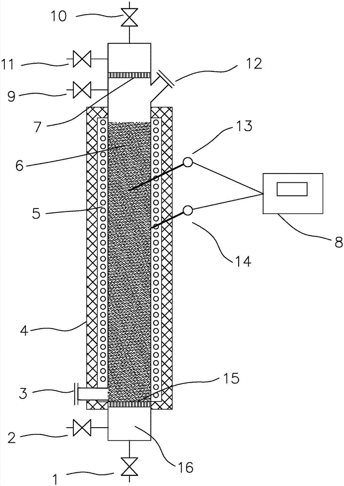
[0036] see figure 1 , which is a schematic structural diagram of a fluorinated graphite tubular reaction furnace of the present invention, the reaction furnace includes: a furnace body, the furnace body from bottom to top is a gas mixing chamber 16, a lower filter layer 15, a reaction chamber 16 and Upper filter layer 7.

[0037] A nitrogen gas inlet 2 and a fluorine gas inlet 1 are respectively provided on the lower wall of the gas mixing chamber 16 , and the nitrogen gas and fluorine gas entering through the nitrogen gas inlet 2 and the fluo...


PUM


Abstract

The invention relates to a fluorinated graphite tubular reactor which comprises a reactor body. The reactor body is internally provided with a gas mixing chamber, a lower filter layer, a reaction cavity and an upper filter layer sequentially from bottom to top. The lower portion of the gas mixing chamber is provided with a nitrogen inlet and a fluorine gas inlet; both the lower filter layer and the upper filter layer are sintered filter sieves; a heater is arranged on the outer side of the reaction cavity; an emptying valve is arranged at the top of the reactor body. The fluorinated graphite tubular reactor has advantages that high fluorination efficiency is achieved due to completeness in contact of graphite and fluorine gas; by arbitrary stacking of graphite in the reactor, the graphite layer thickness is increased, the utilization rate of the reaction cavity is high, and yield of each reactor is increased; in a production process, after fluorination in each reactor is finished, heating stopping of the reactor body is avoided in processes of discharging, new material replacement and supplementation, so that halting-free continuous production is realized, and operation efficiency is improved.

Description

technical field [0001] The invention belongs to the technical field of fluorine chemical industry, and specifically relates to a fluorinated graphite tubular reaction furnace used for converting and producing fluorinated graphite in a fluorinated graphite production process. Background technique [0002] In current industrial production, the preparation method of fluorinated graphite is mainly fluorination reaction of fluorine gas and graphite in a high temperature reaction furnace. The existing graphite fluorination reaction furnace is a horizontal furnace, the raw graphite is spread out and placed in a tube, and the reactor is provided with a heating device to heat the raw material to the required temperature. Fluorine gas enters from one end and reacts with graphite at high temperature to form graphite fluoride. The reaction furnace has the following problems: 1) The conversion rate of fluorine gas is not high. Due to the horizontal placement, the fluorine gas passes thr...

Claims


Application Information

Patent Timeline
Patent Type & Authority Applications(China)
IPC IPC(8): C01B32/10
CPCC01P2006/90C01P2006/10C01P2006/60C01P2006/40Y02P20/10
Inventor 韩保国崔武孝阎晓冬
Owner 洛阳森蓝化工材料科技有限公司
Why Eureka
Try Eureka