Unequal power divider based on microstrip ridge-type gap waveguide

A technology of power divider and gap waveguide, which is applied in the field of electronics, can solve the problem of unequal power distribution and phase adjustment of gap waveguide, and the method of power distribution ratio adjustment and phase matching of microstrip gap waveguide, which is not mentioned. Issues such as unequal power distribution and phase matching method of microstrip ridge-shaped gap waveguide achieve the effects of easy processing and integration, excellent transmission performance, and low insertion loss

Inactive Publication Date: 2017-09-05
NANJING UNIV OF SCI & TECH
View PDF2 Cites 13 Cited by
  • Summary
  • Abstract
  • Description
  • Claims
  • Application Information

AI Technical Summary

Problems solved by technology

[0005] In 2014, Seyed Ali Razavi and Per-Simon Kildal published "2×2-Slotelement for 60-GHz planar array antenna realized on two doubled -sided PCBsusing SIW cavity and EBG-type soft surface fed by microstrip-ridge gapwaveguide”, in which multiple one-to-four microstrip gap waveguides are cascaded into a feed network as a feed structure for a 2*2 antenna subarray, but The method of power distribution ratio adjustment and phase matching of microstrip gap waveguide is not proposed in this paper
[0006] In 2015, Cao Baolin, Wang Hao and others published "High-Gain L-Probe Excited SubstrateIntegrated Cavity Antenna Array with LTCC-Based Gap Waveguide" in IEEE transactions on antennas and propagation journal (vol.63, no.12, December 2015). Feeding Network for W-Band Application", used LTCC technology to realize the equal power distribution structure of the gap waveguide, and realized wider bandwidth and phase matching, but also did not propose the unequal power distribution and phase adjustment method of the gap waveguide
[0007] It can be seen from the above that although the existing technology realizes the equal power distribution design of the microstrip ridge gap waveguide as the feed network, the above-mentioned articles and the existing published articles and patents do not mention the unequal power distribution of the microstrip ridge gap waveguide. Power distribution and phase matching method

Method used


Image

  • Unequal power divider based on microstrip ridge-type gap waveguide
  • Unequal power divider based on microstrip ridge-type gap waveguide
  • Unequal power divider based on microstrip ridge-type gap waveguide

Examples


Embodiment 1

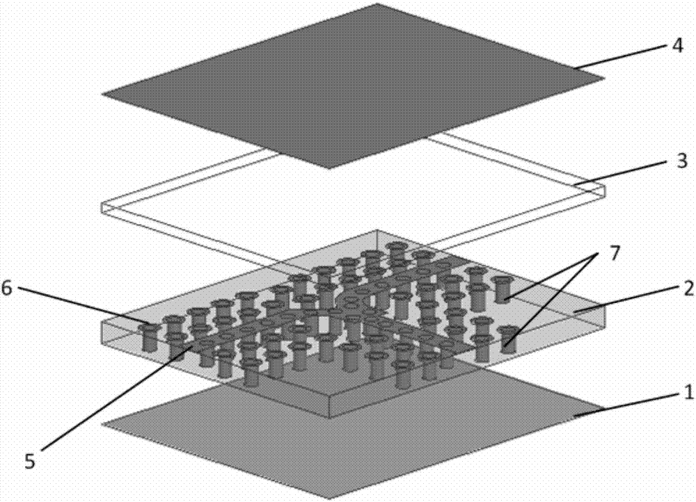
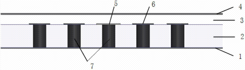
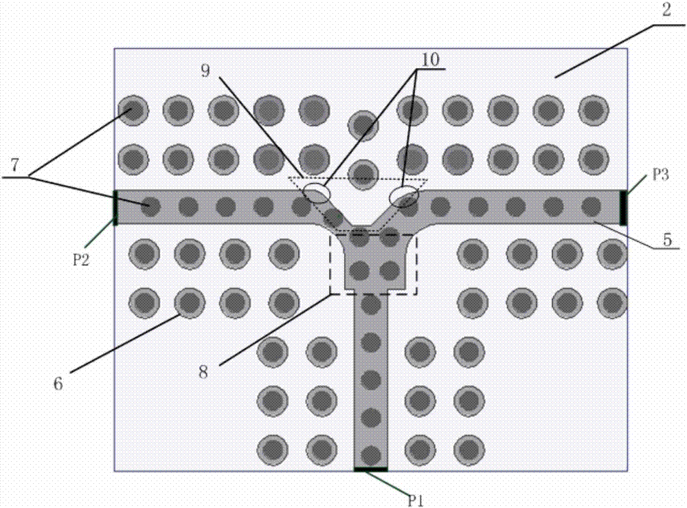
[0037] The three-dimensional structure of the unequal power divider based on the microstrip ridge gap waveguide is as follows: figure 1 As shown, the cross-sectional view is shown in figure 2 As shown, the top view is as image 3 As shown, the relevant dimensions and specifications are as follows Figure 4 shown. The dielectric plate 2 used is Rogers RO4003 dielectric material with a relative permittivity of 3.55 and a loss tangent of 0.0027, with a size of 5.6mm×6.8mm×0.406mm. The gap layer 3 is filled with air, and the thickness is 0.2mm. The size parameters of the microstrip ridge gap waveguide unequal power divider are as follows: W=0.8mm, L=1.1mm, l1=0.45mm, w1=0.25mm, w2=0.5 mm, R=0.45mm, r1=0.2mm, r2=0.75mm, a=0.125mm, b=0.2mm.

[0038] This example is based on the microstrip ridge gap waveguide unequal power divider is modeled and simulated in the electromagnetic simulation software HFSS.13. Figure 5 It is the S-parameter simulation diagram of the unequal power ...


PUM


Abstract

The invention discloses an unequal power divider based on a microstrip ridge-type gap waveguide. The unequal power divider is composed of a dielectric plate of a through hole layer, an air gap layer and a metal cover plate on the air gap layer. The unequal power divider concretely comprises printed microstrip lines in the upper surface of the dielectric substrate, periodic metal pasters, periodic metalized through holes and a metal grounding plate, the metal grounding plate is in the lower surface of the dielectric plate of the through hole layer, and an air gap of certain height is left between the dielectric plate of the through hole layer and the metal cover plate in the upper layer; the microstrip lines are in short connection to the grounding plane via the metalized through hole arranged in a periodic way to form a micrstrip ridge type structure; and the metalized holes arranged in the periodic way are arranged in the surrounding of the printed microstrip line structure, and each metalized hole and the metal paster in the corresponding position form an EBG structure. Thus, problems in unequal power distribution ratio adjustment and phase adjustment of the microstrip ridge-type waveguide are solved, and the unequal power divider also has the advantages of being simple in structure, easy to integrate, easy to process, small in size, wide in bandwith, low in insertion loss and stable in structural performance.

Description

technical field [0001] The invention relates to the field of electronic technology, in particular to an unequal power divider based on a microstrip ridge gap waveguide. Background technique [0002] For the millimeter wave band, especially the frequency band above 60 GHz, the traditional microstrip line and coplanar waveguide and other planar transmission lines will have high insertion loss due to dispersion and loss of dielectric materials, and due to size limitations, the processing accuracy On the other hand, rectangular waveguides and coaxial transmission lines are used due to low loss at high frequencies, but there are still problems in millimeter wave bands with complex machining techniques, high costs, and difficulty in integrating with active microwave electronic circuits . [0003] In 2009, Professor P.-S.Kildal from Sweden published "Waveguides based on local metamaterials in the gap between parallel metal plates" on IEEE Antenna and Wireless Propagation Letters (...

Claims


Application Information

Patent Timeline
Patent Type & Authority Applications(China)
IPC IPC(8): H01P5/12
CPCH01P5/12
Inventor 王昊郑玉雪曹建银季爽
Owner NANJING UNIV OF SCI & TECH
Why Eureka
Try Eureka