
Rotary flexible beam rigidness and softness coupling system vibration measuring and controlling device and method

A rigid-flexible coupling and rotation-flexible technology, which is applied in measuring devices, vibration testing, and machine/structural component testing, can solve problems that threaten spacecraft operation safety, system performance degradation, and affect spacecraft performance. The effect of low energy consumption and convenient control

Active Publication Date: 2017-09-08
CHONGQING UNIV
View PDF5 Cites 18 Cited by
  • Summary
  • Abstract
  • Description
  • Claims
  • Application Information

AI Technical Summary

Problems solved by technology

If these vibrations cannot be quickly suppressed, the stability and pointing accuracy of the spacecraft will be affected, resulting in a decrease in system performance, and even a direct threat to the operational safety of the spacecraft.
Although the vibration control of spacecraft with large-scale appendages has received extensive attention at home and abroad, there are relatively few studies on the small-amplitude rigid-flexible coupling vibration near the equilibrium point caused by the large-scale appendages. Vibration often further induces micro-vibrations of spacecraft in actual aerospace work, affecting the performance of spacecraft, especially high-precision spacecraft

Method used


Image

  • Rotary flexible beam rigidness and softness coupling system vibration measuring and controlling device and method
  • Rotary flexible beam rigidness and softness coupling system vibration measuring and controlling device and method
  • Rotary flexible beam rigidness and softness coupling system vibration measuring and controlling device and method

Examples


Embodiment Construction

[0034] The preferred embodiments of the present invention will be described in detail below with reference to the accompanying drawings.

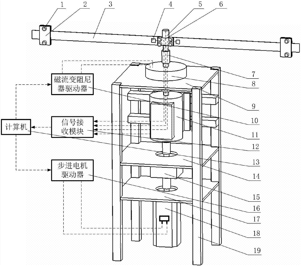
[0035] Such as figure 1 As shown, the vibration measurement device of the rotating flexible beam rigid-flexible coupling system includes the counterweight flexible collar part, the vibration and its interference signal detection part, the stepper motor drive control part and the magnetorheological damper vibration control part;

[0036] ——Counterweight flexible beam part:

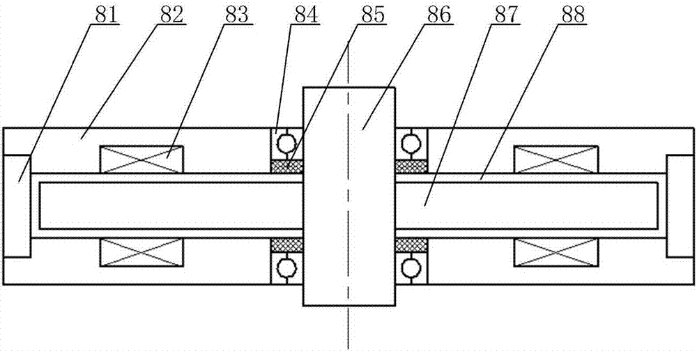
[0037] The counterweight flexible beam system consists of two flexible beams (3) with movable masses (2). One end of the flexible beams (3) fixes the mass (2), and the other end is connected to The rigid transmission shaft is connected by the output shaft of the harmonic reducer (15), the input and output shaft of the torque sensor (11), the input and output shaft of the magnetorheological damper (8), and the mechanical clamping device (6). The shaft is formed by a rig...


PUM


Abstract

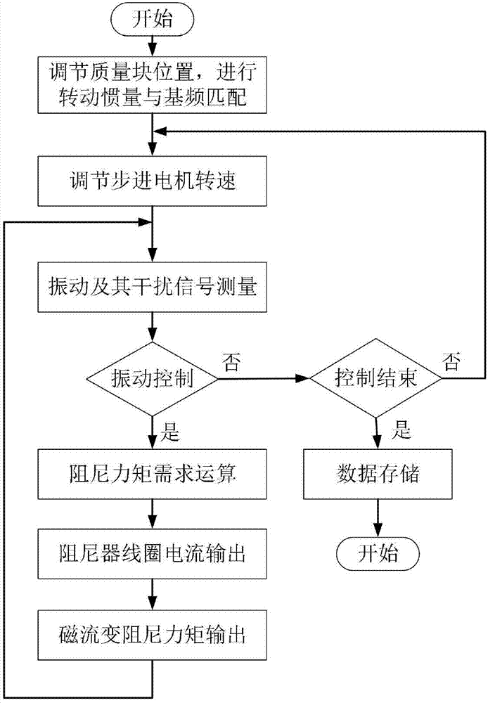
The invention relates to a rotary flexible beam rigidness and softness coupling system vibration measuring and controlling device and a method, which belong to the flexible beam vibration control field. The device comprises a counterweight flexible beam part, a vibration and vibration anti-interference signal detection part, a stepping motor driving and controlling part, and a magneto-rheological damp vibration controlling part. One end of the counterweight flexible beam is fixedly arranged on a rigid transmission shaft through a clamping device, and is driven by the stepping motor to make rotation movement. The position of a mass block on the flexible beam can be adjusted so as to change the base frequency and the moment of inertia of the flexible beam. A strain foil is plastered on the flexible beam close to the root part of a machine tightening device to detect the bending vibration of the flexible beam. The device and the method of the invention are used to simulate the vibrations caused by the driving instability of the space flexible rotation components and to measure and control the interference. Integrated with the signal feedback of multiple sensors and the magneto-rheological controllable damping vibration suppression technology and through the corresponding algorithm, the device and the method realizes the half-active control to the vibration of a low speed rotary flexible beam rigidness and softness coupling system.

Description

technical field [0001] The invention belongs to the field of vibration control of flexible beams, and relates to a vibration measurement and control device and method for a rigid-flexible coupling system of a rotating flexible beam. Background technique [0002] The rotating flexible beam system model is widely used in practical engineering, especially in the application of spacecraft with large-scale accessories, such as spacecraft with large-scale solar wings and antennas. This type of attachment has a large expansion area, and the center of mass is far away from the spacecraft body. It has the characteristics of large span, thin thickness, low stiffness, and weak damping. During the space work of the spacecraft, this type of attachment is susceptible to vibration caused by various disturbances. If these vibrations cannot be quickly suppressed, the stability and pointing accuracy of the spacecraft will be affected, resulting in a decrease in system performance, and even a ...

Claims


Application Information

Patent Timeline
IPC IPC(8): G01M7/02
CPCG01M7/022
Inventor 卢少波张金龙时军委岑胜
Owner CHONGQING UNIV
Learn More