Catalyst recovery process

A catalyst and process technology, applied in the field of catalyst recovery process, can solve the problems of high energy consumption, complex catalyst recovery process, low catalyst recovery rate, etc., and achieve the effects of simplifying the process flow, saving water consumption and reducing energy consumption

Inactive Publication Date: 2017-09-15
ENN SCI & TECH DEV
View PDF6 Cites 6 Cited by
  • Summary
  • Abstract
  • Description
  • Claims
  • Application Information

AI Technical Summary

Problems solved by technology

[0004] In view of this, the present invention proposes a catalyst recovery process aimed at solving the problem

Method used


Image

  • Catalyst recovery process
  • Catalyst recovery process
  • Catalyst recovery process

Examples


Embodiment 1

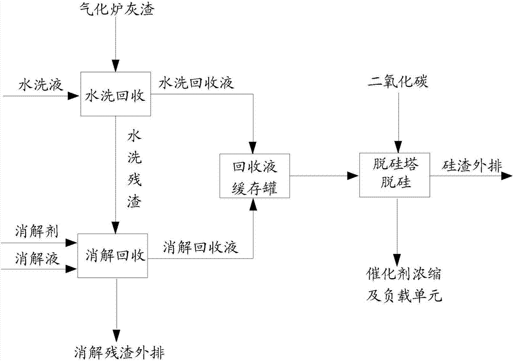
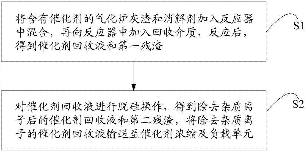
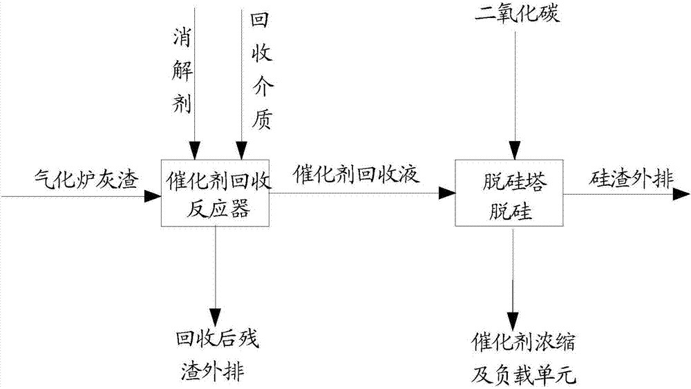
[0044] At a temperature of 180°C and a pressure of 0.2MPa, take 1Kg of gasifier ash and 0.3Kg of Ca(OH) 2 Put it into the reactor and mix evenly, then add 4Kg of deionized water to the reactor, react for 2h under stirring, and recover the water-soluble catalyst and the water-insoluble catalyst at the same time. After the recovery reaction is completed, after the reaction residue is separated from the catalyst recovery liquid, the catalyst recovery liquid is transported to the desiliconization tower and heated to 30°C. After the recovery liquid is desiliconized by the desiliconization tower, the residue liquid is filtered and separated Recovery liquid and silicon slag. The recovered liquid directly enters the concentration unit for concentration, and the concentrated catalyst solution is sent to the supporting unit for catalyst loading. The catalyst recovery rate and the concentration of impurity ions in the catalyst solution after desiliconization were measured, and the results...

Embodiment 2

[0046] At a temperature of 280℃ and a pressure of 0.3MPa, take 0.5Kg of gasifier ash and 0.02Kg of Ca(OH) 2 Put it into the reactor and mix evenly, then add 3Kg of tap water to the reactor, react for 0.5h under stirring, and at the same time recover the water-soluble catalyst and the non-water-soluble catalyst. After the recovery reaction is completed, after the reaction residue is separated from the catalyst recovery liquid, the catalyst recovery liquid is transported to the desiliconization tower and heated to 40°C. After the recovery liquid is desiliconized by the desiliconization tower, the residue liquid is filtered and separated Recovery liquid and silicon slag. The recovered liquid directly enters the concentration unit for concentration, and the concentrated catalyst solution is sent to the supporting unit for catalyst loading. The catalyst recovery rate and the concentration of impurity ions in the catalyst solution after desiliconization were measured, and the results...

Embodiment 3

[0048] At a temperature of 120°C and a pressure of 4MPa, take 1Kg of gasifier ash and 0.5Kg CaO into the reactor and mix them evenly, then add 2Kg of wastewater from the washing tower to the reactor, and react under stirring 5h, recover both water-soluble catalyst and non-water-soluble catalyst at the same time. After the recovery reaction is completed, after the reaction residue is separated from the catalyst recovery liquid, the catalyst recovery liquid is transported to the desiliconization tower and heated to 50°C. After the recovery liquid is desiliconized by the desiliconization tower, the residue liquid is filtered and separated Recovery liquid and silicon slag. The recovered liquid directly enters the concentration unit for concentration, and the concentrated catalyst solution is sent to the supporting unit for catalyst loading. The catalyst recovery rate and the concentration of impurity ions in the catalyst solution after desiliconization were measured, and the resul...


PUM


Abstract

The present invention provides a catalyst recovery process, which comprises: adding gasification furnace ash residue containing a catalyst and a digestion agent to a reactor, uniformly mixing, adding a recovery medium to the reactor, carrying out a reaction, and separating to obtain a catalyst recovery liquid and first residue; and carrying out desilication operation on the catalyst recovery liquid to obtain an impurity-ion-removing catalyst recovery liquid and second residue, and conveying the impurity-ion-removing catalyst recovery liquid to a catalyst concentration and loading unit. According to the present invention, with the process, the simultaneous recovery of the water-soluble catalyst and the insoluble catalyst is achieved, the water washing and the pressure filtration during the digestion are eliminated so as to simplify the process, the agglomeration phenomenon generated during the mixing of the digestion agent and the gasification furnace ash residue being subjected to the water washing is avoided so as to complete reaction and improve the catalyst recovery rate, and the water consumption in the water washing link is eliminated so as to save the water resource, improve the catalyst metal ion concentration in the recovery liquid, and reduce the energy consumption of the catalyst concentration unit.

Description

Technical field [0001] The invention relates to the technical field of coal catalytic gasification, in particular to a catalyst recovery process. Background technique [0002] Coal catalytic gasification is a process in which coal and water vapor react under the action of a catalyst to produce methane-rich coal gas and high value-added oil products. The role of the catalyst is to promote the water-coal reaction and the methanation reaction to achieve the purpose of increasing the carbon conversion rate and methane yield per unit time. Studies have shown that alkali metal catalysts, especially potassium catalysts, have low temperature performance and good catalytic performance for water gas shift and methanation reactions, but they are easy to react with minerals in coal and / or ash, especially oxides of silicon and aluminum. The formation of inert compounds leads to the deactivation of the catalyst; and the cost of potassium catalyst is higher. Therefore, the recovery of the cat...

Claims


Application Information

Patent Timeline
IPC IPC(8): B01J23/04B01J27/232
CPCB01J23/04B01J27/232
Inventor 芦涛毛燕东刘雷李克忠
Owner ENN SCI & TECH DEV
Why Eureka
Try Eureka