
Transimpedance amplifier applied to high-speed optical receiver and design method

A technology of transimpedance amplifiers and optical receivers, which is applied in the direction of light-controlled amplifiers, DC-coupled DC amplifiers, amplifiers with only semiconductor devices, etc., and can solve the problems of difficult to improve the noise performance of high-speed transimpedance amplifiers

Inactive Publication Date: 2017-09-15
XI AN JIAOTONG UNIV
View PDF7 Cites 5 Cited by
  • Summary
  • Abstract
  • Description
  • Claims
  • Application Information

AI Technical Summary

Problems solved by technology

However, high bandwidth and low noise are generally mutually exclusive, so it is difficult to improve the noise performance of high-speed transimpedance amplifiers

Method used


Image

  • Transimpedance amplifier applied to high-speed optical receiver and design method
  • Transimpedance amplifier applied to high-speed optical receiver and design method
  • Transimpedance amplifier applied to high-speed optical receiver and design method

Examples


Embodiment Construction

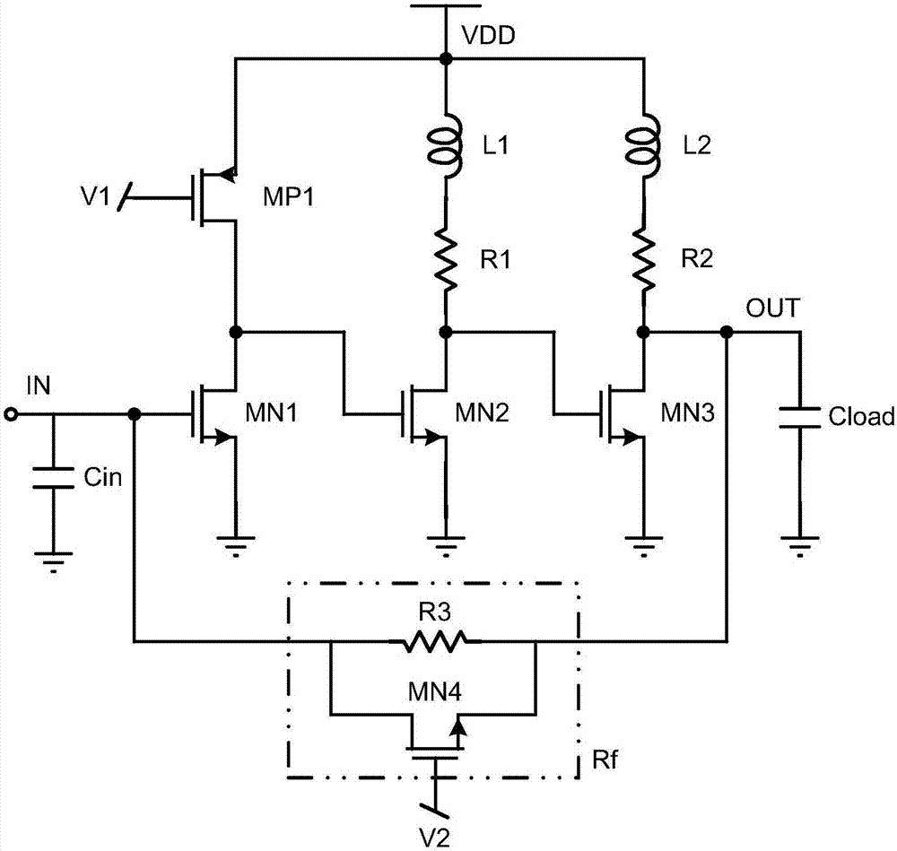
[0026] In order to make the purpose, technical scheme and advantages of the present invention clearer, the following will be combined with the attached figure 2 Embodiments of the present invention are further described in detail.

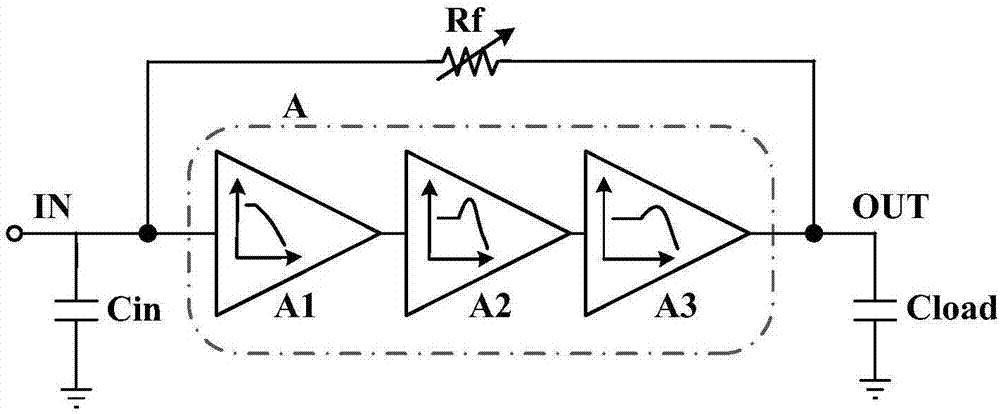
[0027] see figure 1 As shown, a transimpedance amplifier applied to a high-speed optical receiver of the present invention includes: a three-stage high-gain amplifier A, the three stages of which are respectively A1, A2, and A3, and a variable feedback resistor Rf.

[0028] The connection method is: one end of the equivalent input capacitance Cin is connected to the input end of the first-stage amplifier A1, and the other end of the equivalent input capacitance Cin is grounded; the output terminal of the first-stage amplifier A1 of the three-stage amplifier A is connected to the second-stage amplifier A2 The input end of the second-stage amplifier A2 is connected to the input end of the third-stage amplifier A3; the two ends of the feedback resis...


PUM


Abstract

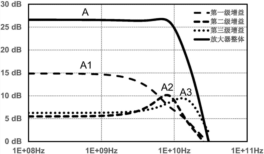
The invention discloses a transimpedance amplifier applied to a high-speed optical receiver and a design method. The transimpedance amplifier comprises a three-level high gain amplifier A and a feedback resistor Rf. The three-level high gain amplifier A comprises a first-level amplifier A1, a second-level amplifier A2 and a third-level amplifier A3. The output end of the first-level amplifier A1 is connected with the input end of the second-level amplifier A2. The output end of the second-level amplifier A2 is connected with the input end of the third-level amplifier A3. Two ends of the feedback resistor Rf are connected with the input end of the first-level amplifier A1 and the output end of the third-level amplifier A3. According to the transimpedance amplifier, a structure of reducing bandwidth and then increasing the bandwidth is employed in the amplifier of the TIA (Transimpedance Amplifier), so under the condition of ensuring the bandwidth required by a system transmission rate, the transimpedance gain of the TIA is improved, and the equivalent input noise of the TIA is reduced.

Description

technical field [0001] The invention relates to the technical field of optical communication chips, in particular to a transimpedance amplifier applied to a high-speed optical receiver. Background technique [0002] In an optical communication system, the current signal generated by the photodetector (photodiode) at the receiving end may be very weak, and the function of the optical receiver preamplifier is to perform transimpedance conversion and amplify the photocurrent signal into a voltage signal of a certain amplitude. , for the subsequent circuit to perform signal processing in the voltage domain. Therefore, the preamplifier in the high-speed optical communication system is called a transimpedance amplifier (Transimpedance Amplifier, hereinafter referred to as TIA). Under the premise that the bandwidth meets the system transmission rate, the transimpedance amplifier is not only required to have low noise, but also to provide sufficient gain to amplify the signal and s...

Claims


Application Information

Patent Timeline
IPC IPC(8): H03F1/26H03F1/32H03F1/48H03F3/08H03F3/45H03G3/30H04B10/69
CPCH03F1/26H03F1/3211H03F1/483H03F3/082H03F3/45179H03G3/3084H04B10/693H03F2200/36H03F2200/372H03F2203/45032
Inventor 李丹刘明耿莉
Owner XI AN JIAOTONG UNIV
Learn More