Offshore crane heave compensation control system and method using video rangefinding
A heave compensation and offshore platform technology, applied in the field of machinery, can solve problems that are difficult to achieve, high in cost, and dependent on compensation speed
- Summary
- Abstract
- Description
- Claims
- Application Information
AI Technical Summary
Problems solved by technology
Method used
Image
Examples
Embodiment 1
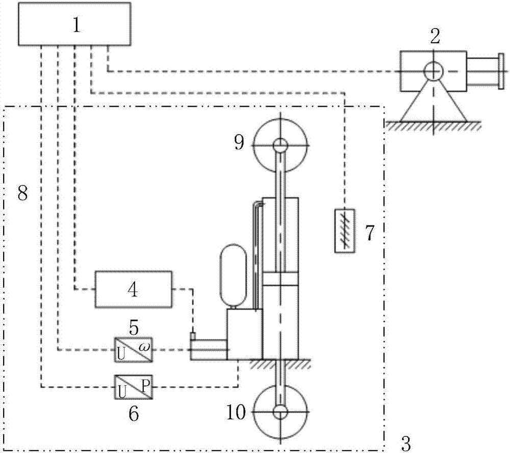
[0062] Such as figure 1 As shown, the heave compensation control system of the offshore platform crane using video ranging according to the present invention includes a control computer 1, an industrial camera 2 and a direct pump-controlled electro-hydraulic heave compensation device 3; an industrial camera 2 and a direct pump-controlled The servo motor driver 4, the speed sensor 5, the three pressure sensors 6 and the built-in displacement sensor 7 in the electro-hydraulic heave compensation device 3 are respectively connected to the control computer 1 through the electrical wiring 8 to exchange information and energy; the industrial camera 2 and the direct pump-controlled electro-hydraulic heave compensation device 3 are respectively installed on the base of the offshore platform crane.
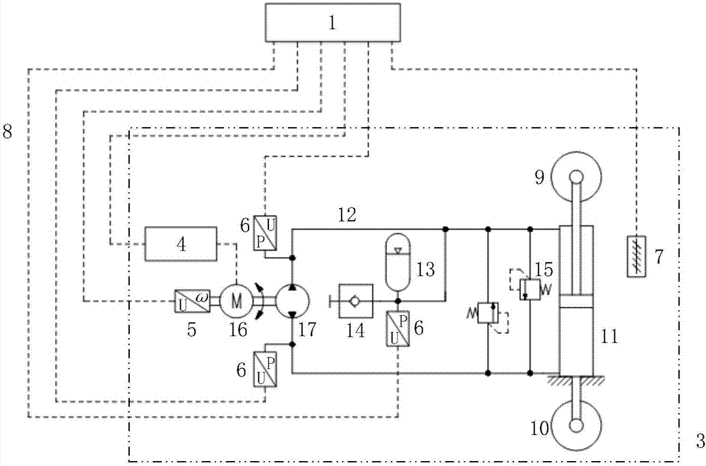
[0063] Such as figure 2 As shown, the first embodiment of the direct pump-controlled electro-hydraulic heave compensation device 3 of the present invention includes a servo motor driver 4...
Embodiment 2
[0071] The present invention provides the direct pump-controlled electro-hydraulic heave compensation device for the heave compensation control system of the offshore platform crane using video ranging, and the direct pump-controlled electro-hydraulic heave compensation device 3 is used as the offshore platform The executive mechanism of the crane heave compensation control system, the direct pump-controlled electro-hydraulic heave compensation device 3 includes a servo motor driver 4, a servo motor 16, a two-way hydraulic pump 17, an accumulator 13, a quick-plug connector 14, two A relief valve 15, a single rod hydraulic cylinder 11, a movable pulley 9, a static pulley 10, at least three pressure sensors 6, a rotational speed sensor 5 and a displacement sensor 7, the servo motor 16 driven by the servo motor driver 4 drives the two-way hydraulic pump 17 to rotate , the two output ends of the two-way hydraulic pump 17 are respectively connected with the rod cavity and the rodles...
Embodiment 3
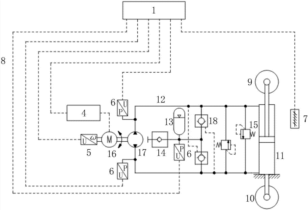
[0082] Such as image 3 Shown is the second embodiment of the direct pump-controlled electro-hydraulic heave compensation device 3 of the present invention, including a control computer 1, a servo motor driver 4, a servo motor 16, a bidirectional hydraulic pump 17, an accumulator 13, Push-in connector 14, two overflow valves 15, single rod hydraulic cylinder 11, movable pulley 9, static pulley 10, three pressure sensors 6, rotational speed sensor 5, built-in displacement sensor 7, hydraulic pipeline 12, electrical connection 8 And two hydraulic control one-way valves 18. Its basic principle is as figure 2 The shown embodiment 1 is the same, and the direct pump-controlled electro-hydraulic heave compensation device 3 can bear negative load through two hydraulically controlled one-way valves 18 . The negative load mentioned above means that the load drives the piston rod of the hydraulic cylinder to move. image 3 In the above, the negative load refers to that the hydraulic ...
PUM
 Abstract
Description
Claims
Application Information
 - R&D
- Intellectual Property
- Life Sciences
- Materials
- Tech Scout
- Unparalleled Data Quality
- Higher Quality Content
- 60% Fewer Hallucinations
Browse by: Latest US Patents, China's latest patents, Technical Efficacy Thesaurus, Application Domain, Technology Topic, Popular Technical Reports.
© 2025 PatSnap. All rights reserved.Legal|Privacy policy|Modern Slavery Act Transparency Statement|Sitemap|About US| Contact US: help@patsnap.com


