Miniaturized capacitive vacuum pressure sensor encapsulation structure

A technology of vacuum pressure and packaging structure, which is applied in fluid pressure measurement using capacitance changes, vacuum gauges, and fluid pressure measurement. It can solve the problems of small electrode plate gap, low overload resistance, and large capacitor electrode diameter. The effect of small force bearing area and high assembly precision

Inactive Publication Date: 2017-10-03
NO 49 INST CHINESE ELECTRONICS SCI & TECH GRP
View PDF5 Cites 5 Cited by
  • Summary
  • Abstract
  • Description
  • Claims
  • Application Information

AI Technical Summary

Problems solved by technology

[0005] The purpose of the present invention is to solve the problem that existing capacitive vacuum sensors have small gaps between electrode plates, large diameters of capacitive electrodes, low overload resistance, and the use of gaseous getters requires the sensor product to be moved out and transferred to other equipment heating, there is a problem of polluting the vacuum degree in the vacuum sealed cavity, and then a miniaturized capacitive vacuum pressure sensor packaging structure is provided

Method used


Image

  • Miniaturized capacitive vacuum pressure sensor encapsulation structure
  • Miniaturized capacitive vacuum pressure sensor encapsulation structure
  • Miniaturized capacitive vacuum pressure sensor encapsulation structure

Examples


specific Embodiment approach 1

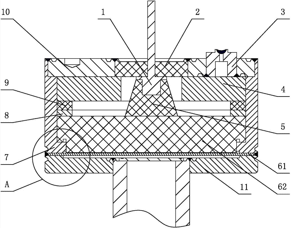
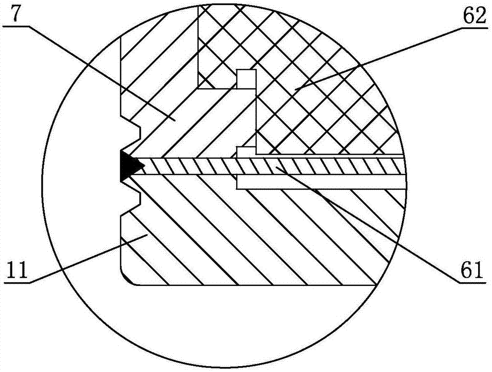
[0025] Specific implementation mode one: combine figure 1 and figure 2 Describe this embodiment, a package structure of a miniaturized capacitive vacuum pressure sensor in this embodiment, which includes a pin 1, an adapter terminal 2, a sealing joint 3, a solid getter 4, a conductive rubber 5, a casing 7, an upper Cover 10, lower cover 11, metal moving electrode 61 and static electrode 62;

[0026] The upper cover 10, the casing 7, the metal moving electrode 61 and the lower cover 11 are arranged in sequence from top to bottom, the lower end surface of the metal moving electrode 61 is fixedly connected to the upper end surface of the lower cover 11, and the upper end surface of the metal moving electrode 61 is connected to the bottom surface of the casing 7. The lower end is fixed, the upper cover 10 is fixedly installed on the upper end of the housing 7, a through hole is opened in the center of the upper cover 10, the transfer terminal 2 is installed in the through hole o...

specific Embodiment approach 2

[0027] Specific implementation mode two: combination figure 1 Describe this embodiment. This embodiment also includes an adjustment gasket 8, which is a metal gasket. Conductive rubber 5 on. With such arrangement, the adjusting washer 8 can ensure the assembly accuracy of the solid getter 4 and the static electrode 62 . Other compositions and connections are the same as in the first embodiment.

specific Embodiment approach 3

[0028] Specific implementation mode three: combination figure 1 Describe this embodiment, this embodiment also includes an insulating washer 9, the insulating washer 9 is a washer made of ceramic material, the insulating washer 9 is installed in the vacuum sealed cavity, the insulating washer 9 is located between the solid getter 4 and the adjusting washer 8 and is set in the Conductive rubber 5 on. In this setting, insulation needs to be done during the signal lead-out process, in order to prevent the introduction of other interference signals. An insulating gasket 9 is added in the vacuum sealed cavity. When the metal coating on the surface of the static electrode 62 is not uniform, the insulating gasket 9 can effectively avoid the introduction of interference signals due to the adjustment of the gasket 8 . Other compositions and connections are the same as those in Embodiment 1 or Embodiment 2.


PUM

PropertyMeasurementUnit
diameteraaaaaaaaaa
thicknessaaaaaaaaaa

Abstract

The invention relates to a miniaturized capacitive vacuum pressure sensor encapsulation structure and belongs to the capacitive vacuum sensor field. The invention aims to solve a problem caused by the narrowness of a gap between electrode plates, the problem of low anti-overload capacity caused by the largeness of the diameter of electrodes and the contamination of vacuum degree in a vacuum sealed chamber which is caused by a condition that an existing capacitive vacuum pressure sensor is required to be transferred to other equipment to be heated due to the utilization of a gas-state getter in the existing capacitive vacuum pressure sensor. According to the miniaturized capacitive vacuum pressure sensor encapsulation structure of the invention, the lower end surface of a metal movable electrode is fixedly connected with the upper end surface of a lower cover; the upper end surface of the metal movable electrode is fixedly connected with the lower end of a housing; the upper cover is fixedly mounted on the upper end of the housing; a change-over terminal is mounted on the upper cover; the outer edge of the change-over terminal is fixedly connected with the upper cover; a fixed electrode is arranged in the housing; the lower end of conductive rubber contacts with the upper end surface of the fixed electrode; one end of a pin is installed in a groove at the upper part of the conductive rubber, and the other end of the pin is fixedly connected with the change-over terminal; and a sealing joint is welded to the upper cover. The miniaturized capacitive vacuum pressure sensor encapsulation structure of the present invention is used for the measurement of vacuum pressure.

Description

technical field [0001] The invention relates to a capacitive vacuum sensor, in particular to a package structure of a miniaturized capacitive vacuum pressure sensor. Background technique [0002] At present, the main principles of using high-sensitivity pressure sensors to make micro-mechanical vacuum sensors are piezoresistive and capacitive. The cost of piezoresistive vacuum sensors is low, but the accuracy is poor; capacitive vacuum sensors are more and more popular because of their advantages such as high measurement accuracy, fast dynamic response, measurement results independent of gas composition, corrosion resistance, and pressure shock resistance. people's attention. It can be used to replace mercury manometers, oil pressure gauges, resistance vacuum gauges, thermocouple vacuum gauges and even partially replace ionization gauges. It can be used in meteorology, aerospace, chemical industry, vacuum smelting, light industry, food and other production and scientific re...

Claims


Application Information

Patent Timeline
Patent Type & Authority Applications(China)
IPC IPC(8): G01L21/00G01L9/12
CPCG01L21/00G01L9/12
Inventor 王凡王洪岩刘宝伟陈宝成孙志成孙帅崔光浩李日东宁金明宗义仲
Owner NO 49 INST CHINESE ELECTRONICS SCI & TECH GRP
Why Eureka
Try Eureka