A compact condensing fuel gas boiler with enhanced heat exchange cascade cooling

A technology for strengthening heat exchange and gas-fired boilers. It is used in steam/steam condensers, combustion using liquid fuels and gaseous fuels, and combustion equipment. Problems such as unreasonable planning of boiler accessory modules to avoid thermal efficiency reduction, reduce the number of tube passes, and eliminate damage

Active Publication Date: 2019-04-16
XI AN JIAOTONG UNIV +1
View PDF6 Cites 0 Cited by
  • Summary
  • Abstract
  • Description
  • Claims
  • Application Information

AI Technical Summary

Problems solved by technology

[0004] 2. Conventional shell-type boilers limit the deep condensation of flue gas due to the lack of cooling water sources; for domestic heating oil-fired gas boilers, the return water / outlet water temperatures are usually set at 70 / 95°C and return water at 70°C It is impossible to condense when the temperature is higher than the water dew point temperature. The designer needs to introduce cold water from outside the boiler system to condense the flue gas, but this part of the heat does not return to the boiler, and sometimes this part of the heat is wasted. To a certain extent, it does not improve the overall thermal efficiency of the boiler;
[0005] 3. Boiler modularization and integration are not enough; the lack of overall layout in the boiler design process leads to unreasonable planning of boiler auxiliary modules. Although some shell boilers also use single-return smoke pipes, in order to reduce the longitudinal length of the boiler, the condensation The heat exchanger is placed on the boiler shell, resulting in the emergence of a large number of backpack boilers on the market, or "Liu Luopan" boilers, whose appearance and size lack aesthetic feeling, and even spoil the scenery

Method used


Image

  • A compact condensing fuel gas boiler with enhanced heat exchange cascade cooling
  • A compact condensing fuel gas boiler with enhanced heat exchange cascade cooling
  • A compact condensing fuel gas boiler with enhanced heat exchange cascade cooling

Examples


Embodiment 1

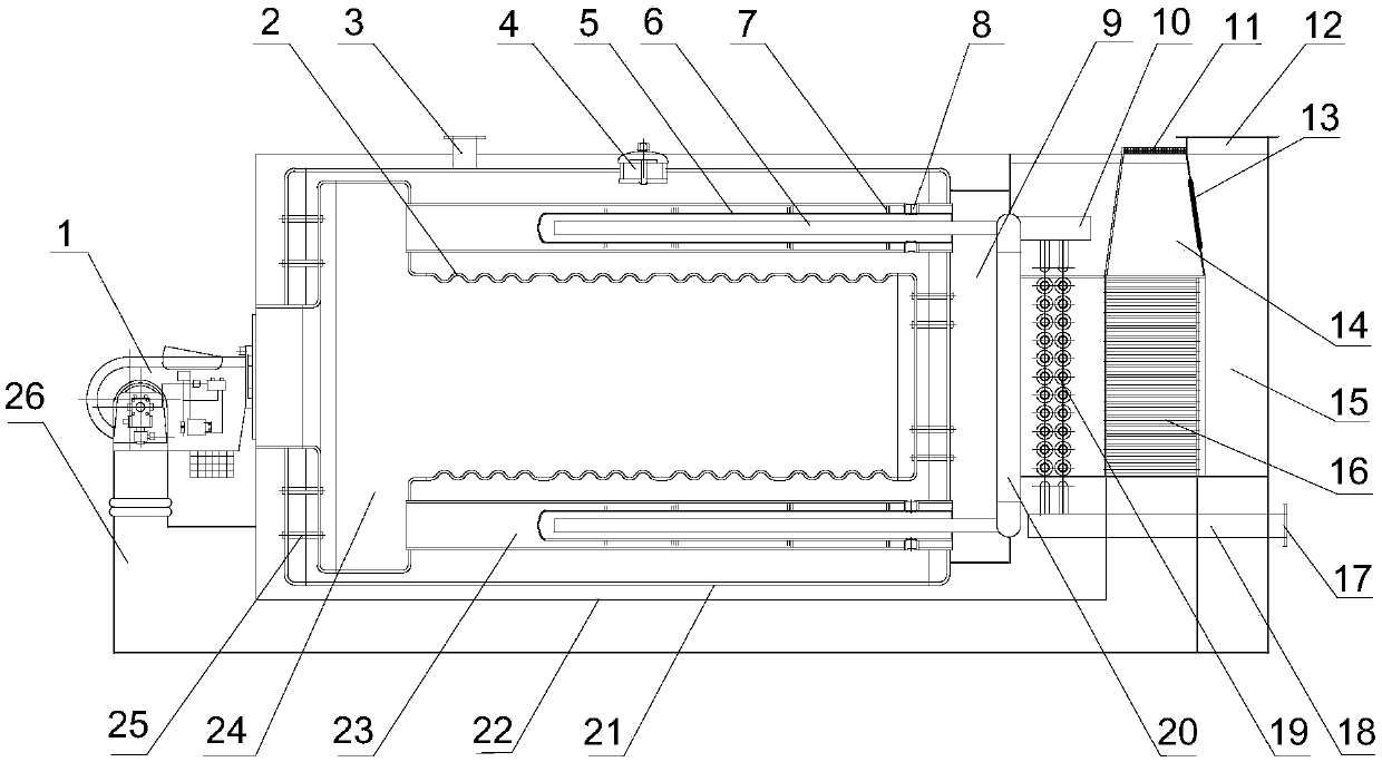
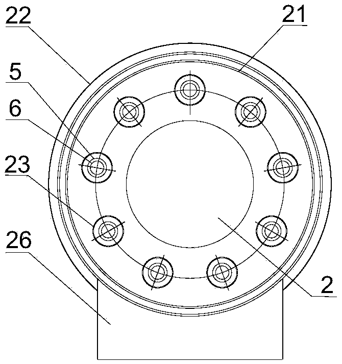
[0047] Such as figure 1 As shown, the present invention is a compactly arranged shell-type fire tube fuel gas steam and hot water boiler equipment, including a new type of smoke tube enhanced heat exchange device, flue gas condensation and flue gas recirculation system; specifically including from outside to inside Boiler shell 22, drum 21 and furnace 2 are arranged in sequence. Manhole 4 is set on boiler shell 22 and drum 21, and fixing device 25 is arranged between drum 21 and furnace 2; Device 1.

[0048] In this embodiment, the burner 1 is a diffuser burner, and the front side of the furnace 2 is covered with a combustion chamber 24, and the furnace 2 and the combustion chamber 24 are connected to form a horizontal T-shaped structure; A plurality of smoke pipes 23 uniformly surrounding are arranged on the outside, and the back combustion chamber 24 communicates with the front ends of the smoke pipes 23 .

[0049] Between the drum 21 and the boiler shell 22, the first flu...

Embodiment 2

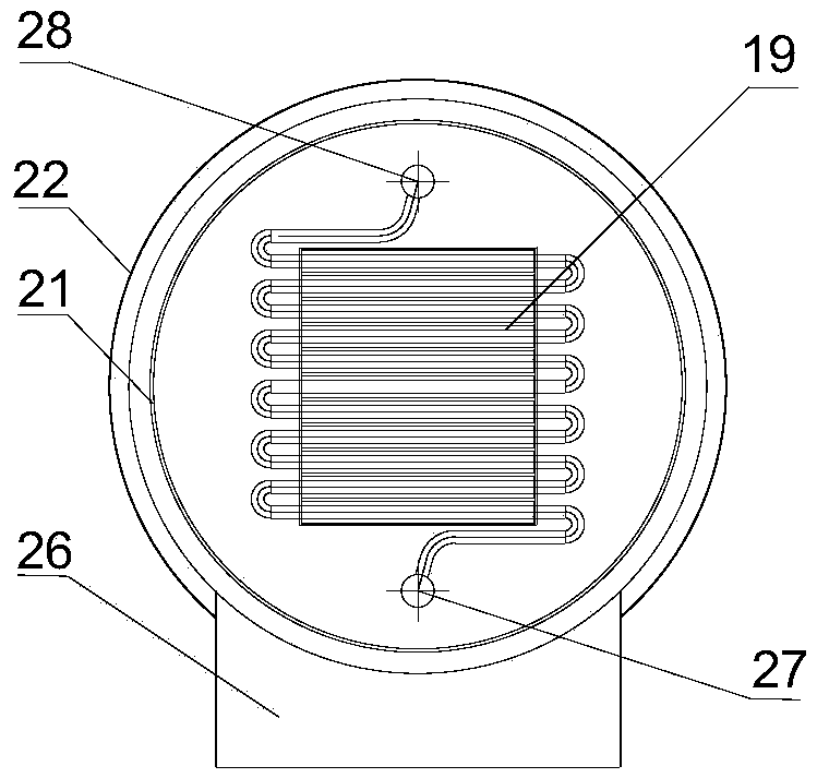
[0064] Such as Figure 7 and Figure 8 As shown, the burner 1 in this embodiment is also a diffuser burner, and the reburning chamber 24 is arranged on the front side of the furnace 2. The combustion chamber 24 is connected; the front end of the furnace 2 and the outlet of the burner 1 are sealed and connected by a sealing baffle 31 ; the smoke pipe 23 surrounds the outside of the furnace 2 evenly.

[0065] Other structures are the same as in Embodiment 1. This embodiment is suitable for boilers with a capacity greater than 8t / h (or 5.6MW).

Embodiment 3

[0067] Such as Figure 9 and Figure 10 As shown, the burner 1 in this embodiment is an ejector type burner, the reburning chamber 24 is sleeved outside the rear of the furnace 2 , and the front ends of the smoke pipes 23 are located at the rear of the furnace 2 .

[0068]Other structures are the same as in Embodiment 1. This embodiment is suitable for burners that produce relatively short flames.

[0069] Main working process and principle of the present invention:

[0070] When the boiler capacity is less than or equal to 8t / h (or 5.6MW), the fuel or gas is mixed with air to burn through the burner 1 and generate flue gas. The burning flame and flue gas move backward along the center of the furnace 2 and pass through the furnace 2. After radiative heat exchange, turn 180° from the center of the rear of the furnace 2 and move forward along the inner wall of the furnace 2. During this period, co-combustion can occur with the central combustion flame, forming a reducing atmo...


PUM


Abstract

The invention relates to a compact condensing type oil-gas boiler with the enhanced heat exchange and cascade cooling functions. The compact condensing type oil-gas boiler with the enhanced heat exchange and cascade cooling functions comprises a boiler shell, a boiler barrel and a boiler container which are sequentially arranged from outside to inside. The boiler container communicates with a backflash chamber. The backflash chamber communicates with multiple smoke pipes. The smoke pipes are arranged in the boiler barrel and located at the rear side of the backflash chamber. An airtight enhanced heat exchange pipe for first-level smoke cooling is arranged in each smoke pipe. A first water return pipe is mounted in each enhanced heat exchange pipe. The first water return pipes are connected with a water return device, and outlets of the first water return pipes are opposite to the inner side walls of the front ends of the corresponding enhanced heat exchange pipes. The rear ends of the enhanced heat exchange pipes communicate with the boiler barrel through water distribution pipes. A hot water or steam outlet is formed in the upper side of the front end of the boiler barrel. A first smoke chamber, a second smoke chamber, a three-level air condenser and a flue which sequentially communicate with one another are arranged between the boiler barrel and the boiler shell from front to rear. A second-level smoke cooler is arranged in the second smoke chamber. The smoke pipes communicate with the first smoke chamber. By the adoption of the compact condensing type oil-gas boiler with the enhanced heat exchange and cascade cooling functions, the temperature of smoke can be lowered effectively, the number of tube passes of the smoke pipes is reduced, and the occupied area is saved.

Description

technical field [0001] The invention relates to the technical field of fuel gas boiler equipment, in particular to a compact condensing fuel gas boiler with enhanced heat exchange cascade cooling. Background technique [0002] In the past ten years, the exploration and development of oil and natural gas have been vigorously developed across the country, and many oil and gas fields with large reserves have been surveyed. At the same time, the country also intends to introduce oil and gas resources from neighboring countries to increase oil and gas supply. In order to improve the environmental pollution and air quality of large and medium-sized cities, governments at all levels encourage enterprises and institutions to gradually replace coal-fired heating sources with fuel oil, especially gas, which undoubtedly once again promotes the development of oil-fired gas-fired boilers. In terms of its body structure, oil-fired gas-fired boilers can be divided into shell-type (fire-tub...

Claims


Application Information

Patent Timeline
Patent Type & Authority Patents(China)
IPC IPC(8): F23C9/00F23C1/08F23J15/06F28B1/06F28B9/08
CPCF23C1/08F23C9/00F23J15/06F28B1/06F28B9/08Y02E20/30
Inventor 邵怀爽赵钦新刘志起梁志远王鹏黄涛
Owner XI AN JIAOTONG UNIV
Why Eureka
Try Eureka