Laser multi-focus dynamic machining method and system
A dynamic processing and multi-focus technology, which is applied in the direction of metal processing equipment, laser welding equipment, manufacturing tools, etc., can solve the difficulty of debugging the same optical axis of each focusing sheet with increased error, the increase of accumulated error of multi-focus lens groups, and the laser Increased energy loss and other issues, to achieve the effect of reducing laser energy loss, increasing thickness, and increasing distance
- Summary
- Abstract
- Description
- Claims
- Application Information
AI Technical Summary
Problems solved by technology
Method used
Image
Examples
example 1
[0044] In this embodiment, one of the laser multi-focus dynamic processing systems of the present invention is used to cut and separate the KDP crystal with a thickness of 100 mm.
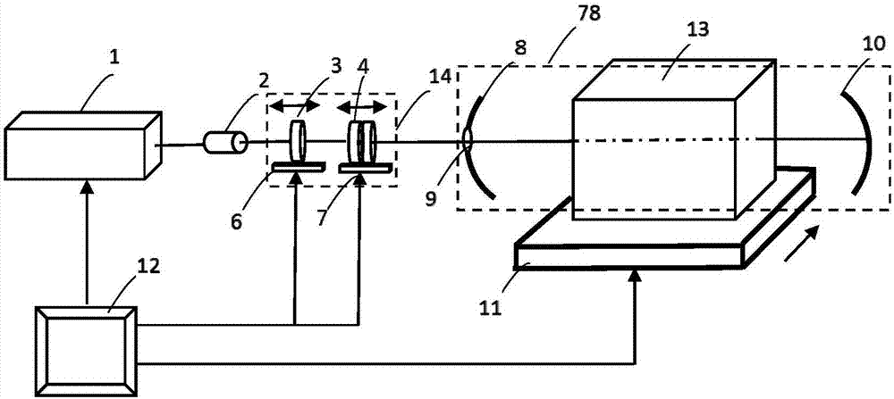
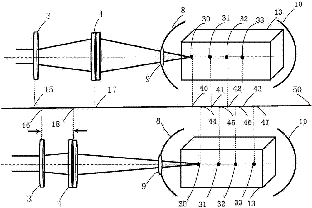
[0045] The laser source in the laser multi-focus dynamic processing system is a fiber continuous laser with a wavelength of 1064nm, an output power of 100W, an output spot diameter of 0.8mm, and a dynamic focusing lens with a focal length of 150mm. The first total reflection mirror in the multi-focus derivative system is a spherical mirror with a diameter of 60 mm, a mirror focal length of 35 mm, and a small hole diameter of 1 mm; the second total reflection mirror is an aspheric mirror with a mirror focal length of 48.5 mm. The transparent material to be processed is KDP crystal (full name in Chinese: potassium dihydrogen phosphate crystal), with a thickness of 100mm and an absorption rate of 5% for a wavelength of 1064nm. The distance from the first total reflection mirror to the surface of the t...
example 2
[0048] In this embodiment, the second laser multi-focus dynamic processing system of the present invention is used to cut and separate soda-lime glass with a thickness of 40 mm.
[0049] The system uses an ytterbium-doped fiber laser with an output wavelength of 1070nm and a peak power of 1000W to cut and separate soda-lime glass with a size of 100mm×100mm and a thickness of 40mm.
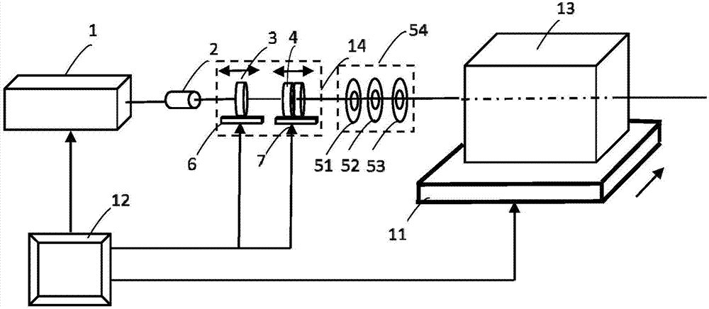
[0050] Experimental method: Three focusing lenses are used to form a multi-focus lens group, and the position and parameters of each laser focusing lens are adjusted to generate four focal points in the soda-lime glass, which are evenly distributed along the thickness direction of the soda-lime glass. The first laser focus generated is located in the soda-lime glass, 5mm away from the incident surface of the material. The energy distribution of the four laser focuses is 20%, 30%, 30%, and 20% respectively, and the distance between each focus is 10mm. The focal length of the dynamic focusing lens is...
example 3
[0053] Two pairs of KDP crystals with a thickness of 200 mm are cut and separated by using the laser multi-focus dynamic processing system of the present invention.
[0054] The laser light source is an all-solid-state green laser with a wavelength of 532nm and a peak output power of 500W. The KDP crystal sample with a size of 500mm×500mm and a thickness of 200mm is cut and separated.
[0055] Experimental method: A multi-focus lens group composed of three focusing lenses is used to adjust the position and parameters of the laser focusing lens so that the focused laser beam produces four laser focuses in the KDP crystal, and the focal distance is 40mm. The distance between the first laser focal point and the incident surface of the KDP crystal is 40mm. The energy distribution of the four laser focal points is 20%, 30%, 25%, and 25%. The laser power is adjusted to 500W, and the laser scanning speed is 0.2mm / s. , scan along a straight line trajectory.
[0056] Experimental resu...
PUM
| Property | Measurement | Unit |
|---|---|---|
| Diameter | aaaaa | aaaaa |
| Thickness | aaaaa | aaaaa |
| Thickness | aaaaa | aaaaa |
Abstract
Description
Claims
Application Information
 - R&D
- Intellectual Property
- Life Sciences
- Materials
- Tech Scout
- Unparalleled Data Quality
- Higher Quality Content
- 60% Fewer Hallucinations
Browse by: Latest US Patents, China's latest patents, Technical Efficacy Thesaurus, Application Domain, Technology Topic, Popular Technical Reports.
© 2025 PatSnap. All rights reserved.Legal|Privacy policy|Modern Slavery Act Transparency Statement|Sitemap|About US| Contact US: help@patsnap.com


