High-isolation circularly polarized balanced radar radio frequency front-end structure

A radio frequency front-end, circular polarization technology, applied in the field of high isolation circular polarization balanced radar radio frequency front-end structure, can solve the problem of not considering the signal energy loss, not considering the transmission signal, reducing the accuracy of the system, etc., to achieve the antenna coupling effect The effect of weakening, simplifying the system structure, and eliminating antenna reflections

Active Publication Date: 2017-10-24
NANJING UNIV OF SCI & TECH
View PDF3 Cites 6 Cited by
  • Summary
  • Abstract
  • Description
  • Claims
  • Application Information

AI Technical Summary

Problems solved by technology

However, there are relatively large defects in the shared antenna structure for transmitting and receiving: due to the limited isolation of the circulator used in the shared transmitting and receiving structure, the transmitted signal will leak to the receiving part, which will reduce the accuracy of the system, and even when the leakage is serious, It will make the system misjudgment, so the problem of emission signal leakage becomes the main obstacle to improve the accuracy of short-range detection radar
Among them, the relatively successful combination of passive leakage cancellation and circular polarization is the circular polarization balanced radar technology proposed by Han Lim Lee et al. in recent years. This technology uses passive modules such as quadrature couplers and Lange couplers , six ports, etc., to replace the circulator with a shared and structurally symmetrical network for transmitting and receiving channels, and to use the structural balance symmetry and rationally allocate th

Method used


Image

  • High-isolation circularly polarized balanced radar radio frequency front-end structure
  • High-isolation circularly polarized balanced radar radio frequency front-end structure
  • High-isolation circularly polarized balanced radar radio frequency front-end structure

Examples


Embodiment

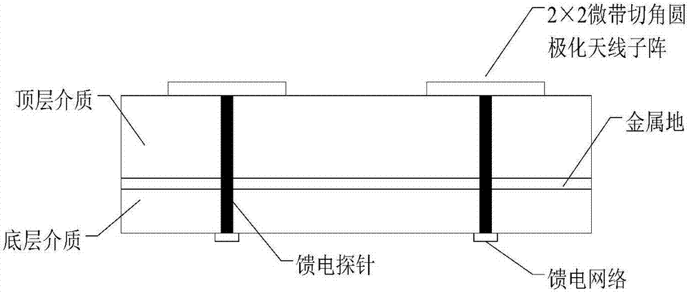
[0032] to combine figure 1 , the top dielectric plate of the high isolation circular polarization balanced radar radio frequency front-end structure of the present embodiment adopts the Rogers 5880 dielectric plate with a dielectric constant of 2.2 and a thickness of 1mm, and the bottom layer adopts a Rogers 4003 with a dielectric constant of 3.55 and a thickness of 0.813mm Dielectric plate, the diameter of the feeding probe is 0.6mm.

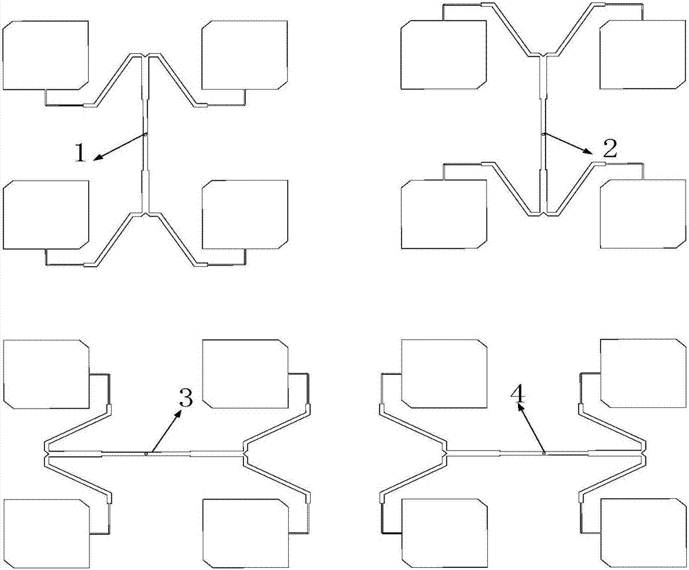
[0033] to combine figure 2 , the top antenna array is composed of four 2×2 microstrip corner-cutting circularly polarized antenna sub-arrays, the length of the right-angled side of the microstrip patch is 2.2mm, and the spacing between the antenna patch elements is 45mm.
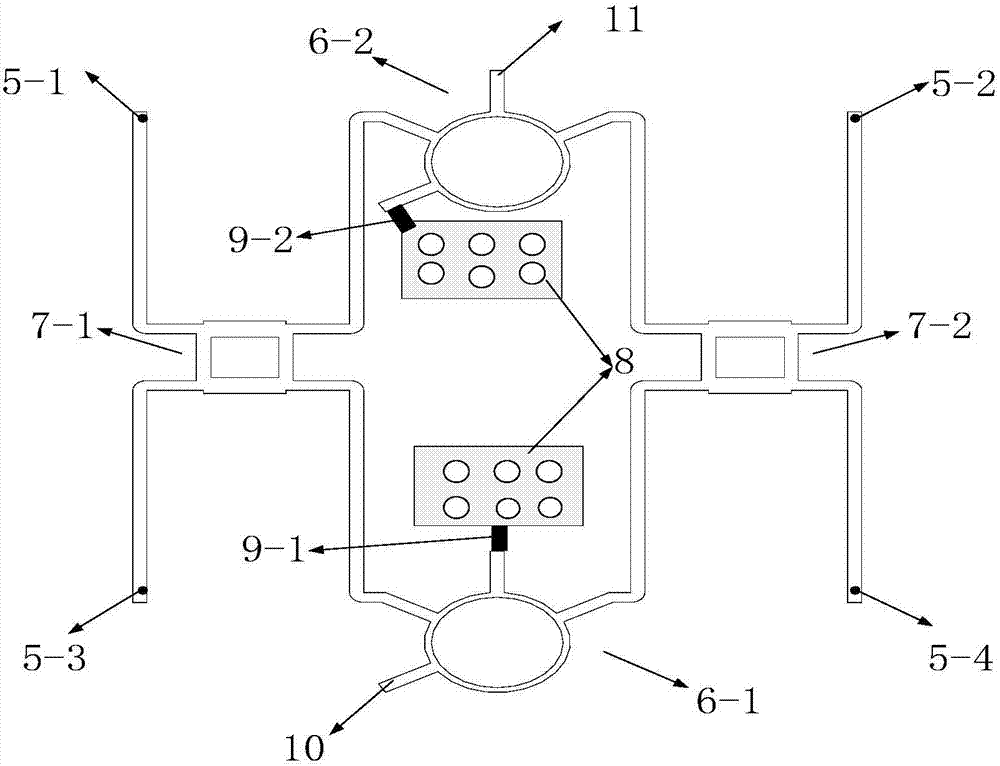
[0034] The resistance values ​​of the two matching resistors, the port characteristic impedances of the two ring couplers, and the port characteristic impedances of the two orthogonal couplers are all 50Ω.

[0035] Figure 4 It is a simulation S parameter diagram of the h...


PUM


Abstract

The invention relates to a high-isolation circularly polarized balanced radar radio frequency front-end structure, which comprises a two layers of dielectric plates, four 2*2 microstrip chamfered circular polarization antenna subarrays arranged on the top dielectric plate and a feed network arranged on the bottom dielectric plate, and is characterized in that and metal bottoms of the two layers of dielectric plates are connected; and the feed network comprises four feed probes, two annular couplers, two quadrature couplers, a grounding patch, two matched resistors, a signal transmitting terminal and a signal receiving terminal. The high-isolation circularly polarized balanced radar radio frequency front-end structure is simple in structure, low in cost and high in reliability, can easily realize good isolation between the transmitting terminal and the receiving terminal and improves the interference resisting ability. Meanwhile, acting as a balanced radar front-end system, the high-isolation circularly polarized balanced radar radio frequency front-end structure can solve problems of antenna reflection and partial coupling while well realizing leakage cancellation, and can be applied to various radar communication and short-range detection occasion requiring shared transmitting and receiving and high isolation.

Description

technical field [0001] The invention belongs to the technical field of radar communication and short-range detection, in particular to a high-isolation circular polarization balance radar radio frequency front-end structure. Background technique [0002] With the development of technologies such as short-range detection, microelectronics, and high-speed signal processing, the short-range detection continuous wave radar has begun to emerge in the civilian field. Life brings great convenience. Generally, in order to obtain a simpler structure, occupy less space, and reduce costs as much as possible, the general short-range detection continuous wave radar adopts a common antenna structure for sending and receiving. The common antenna for transmitting and receiving is an important part of the short-range detection radar, and it is an indispensable device to realize the good performance of the whole system. However, there are relatively large defects in the shared antenna struc...

Claims


Application Information

Patent Timeline
IPC IPC(8): G01S7/35
CPCG01S7/35
Inventor 邾志民陈春红吴文单卿李涛陈云姣张新鹏戴善江
Owner NANJING UNIV OF SCI & TECH
Why Eureka
Try Eureka