Movable acid liquid and acid gas integration treatment device and treatment process thereof
A treatment device and mobile technology, applied in the direction of gas treatment, natural water treatment, water treatment parameter control, etc., can solve the problems of complex installation and cumbersome process, and achieve the effects of low cost, efficient and fast treatment, and fast and convenient pipeline connection
- Summary
- Abstract
- Description
- Claims
- Application Information
AI Technical Summary
Problems solved by technology
Method used
Image
Examples
Embodiment 1
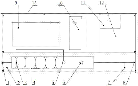
[0023] This embodiment provides a figure 1 The movable integrated treatment device for acid liquid and acid gas shown includes a skid base 13 on which a reactor 4 is installed, and the top of the reactor 4 is provided with a lye injection port 5 and a defoamer injection port 6 , the lye injection port 5 is connected to the alkali injection pump 9 through the pipeline, the defoamer injection port 6 is connected to the defoamer injection pump 10 through the pipeline, and the alkali injection pump 9 and the defoamer injection pump 10 are all installed on the skid base 13 ;
[0024] The inlet end of the reactor 4 is connected with the inlet pipeline, and the mouth of the inlet pipeline is the device inlet 8, and the inlet sampling port 7 is opened near the device inlet 8 on the inlet pipeline, and the outlet end of the reactor 4 is connected with the outlet pipeline, and the outlet pipeline The mouth of the pipe is the device outlet 1, and the outlet sampling port 2 is opened on ...
Embodiment 2
[0029] On the basis of Embodiment 1, it also includes an integrated control cabinet 11 and a tool storage room 12 installed on the skid base 13, and the alkali injection pump 9, the defoamer injection pump 10 and the tool storage room 12 are sequentially along the length direction of the skid base 13 Arranged, the integrated control cabinet 11 is located between the defoamer injection pump 10 and the tool storage room 12 and is arranged close to the long side of the skid seat 13.
[0030] The specific arrangement is as figure 1 , this arrangement makes full use of the space of the skid base 13, and the whole structure is an integrated design. At the same time, according to the actual needs of the site, a lighting system, etc. can be installed on the skid base 13, and can be controlled through the integrated control cabinet 11.
Embodiment 3
[0032] On the basis of Example 1, such as figure 2 As shown, the reactor 4 is divided into a pipeline mixing part 402 and a slow-release part 401, the slow-release part 401 is connected with the inlet pipeline, and the inner cavity of the slow-release part 401 is evenly spaced along the length direction with a plurality of anti-erosion partitions 14. The pipeline mixing part 402 is in communication with the outlet pipeline. The inner cavity of the pipeline mixing part 402 is provided with double helical blades 3 along the length direction.
[0033] The device reactor is divided into a slow release part 401 and a pipeline mixing part 402. The diameter of the slow release part 401 becomes larger to reduce the flow rate, and the anti-erosion partition 14 is used to change the flow direction of the liquid, so that the flowback liquid and the defoamer are fully mixed and reacted; The pipeline mixing part 402 uses double helical blades 3 to fully mix and react the acid liquid, acid...
PUM
 Abstract
Description
Claims
Application Information
 - R&D
- Intellectual Property
- Life Sciences
- Materials
- Tech Scout
- Unparalleled Data Quality
- Higher Quality Content
- 60% Fewer Hallucinations
Browse by: Latest US Patents, China's latest patents, Technical Efficacy Thesaurus, Application Domain, Technology Topic, Popular Technical Reports.
© 2025 PatSnap. All rights reserved.Legal|Privacy policy|Modern Slavery Act Transparency Statement|Sitemap|About US| Contact US: help@patsnap.com


